 |
|||
|
|
|||
|
Page Title:
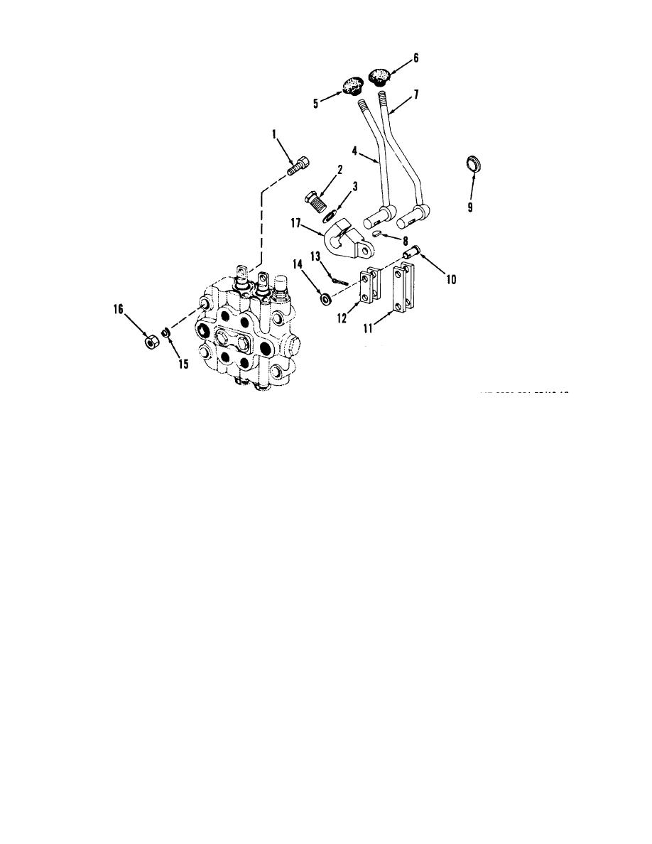
Figure 10-13. Control levers, exploded view |
|
||
| ||||||||||
|
|
 TM 10-3930-621-34
ME 3930-621-35/10-13
1.
Screw
10.
Pin
2.
Bolt
11.
Lift link
3.
Lock washer
12.
Tilt link
4.
Tilt handle
13.
Cotter pin
5.
Red tilt knob
14.
Flat washer
6.
Black lift knob
15.
Flat washer
7.
Lift handle
16.
Nut
8.
Key
17.
Lever
9.
plug
Figure 10-13. Control levers, exploded view
c. Place cowl plugs (9) on handle shafts and insert
10-52. Cleaning, Inspection, and Replacement
handles (4 and 7) in cowl. Press cowl plugs in place.
a. Clean all parts with cleaning compound, solvent
d. Install woodruff keys (8) in slot in handle shafts
(Spec. P-S-661) and dry thoroughly with compressed
and slide on control levers (17).
air.
e. Secure levers (17) to handle shafts with bolts (2)
b. Inspect all contact surfaces for cracks, bends,
and lock washers (3).
corrosion, or other damage which could impair valve
f. Place handles in forward position and install links
return spring action.
(11 and 12) on control levers (17) and control valve
c. Replace defective parts as authorized.
plungers and secure with pins (10), washers (14), and
10-53. Installation
cotter pins (13).
a. Refer to figure 10-13 and install as follows: b.
Note. Tilt link (12) is shorter than lift link (11).
Being careful to install correct knob color on handle,
g. Install right side cowl on truck (TM 10-3930-621-
install red (tilt) handle knob (5) and black (lift) handle
12).
knob (6) on respective handles.
10-29
|
|
Privacy Statement - Press Release - Copyright Information. - Contact Us |
