 |
|||
|
|
|||
|
Page Title:
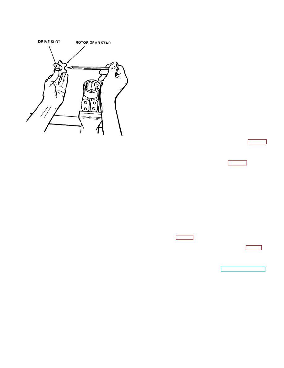
Figure 9-5. Drive-gear alinement. |
|
||
| ||||||||||
|
|
 TM 10-3930-621-34
(9) Secure assembly in vise and torque screws
to 150 inch-pounds.
e. Column.
(1) Note match-marks on column (36) and
secure column to mounting plate (17) with bolts (37).
Torque bolts to 280 inch-pounds.
(2) Install retaining ring (31), bearing (30), and
retaining ring (26) on shaft (32).
(3) Insert horn wire (33) through washer (27),
spring, ferrule (25), and partially through shaft (32).
Bring wire out from shaft and attach to contact ring (34).
(4) Insert insulator (35) in contact ring (34) and
slide both, gradually pulling back on horn wire, on shaft
(32).
(5) Insert shaft (32) in column (36) and secure
with retaining ring (28). Rotate shaft to engage shaft and
spool splines.
(6) Install brush assembly (15) on column (36)
securing with screws (14).
(7) Install connector (13) on brush wire.
(8) Install steering gear support (22, fig. 8-3)
with brake pedal stop on steering column and secure it to
ME 3930-621-35/9-5
steering gear with two screws (2) and lock washers (1).
f. Horn Button.
Figure 9-5. Drive-gear alinement.
(1) Thread horn wire (33, fig. 9-1) through
steering wheel (12), lock washer (11), nut (10), washer
(6) Push splined end of drive (23) through the
(9), and spring (8) and attach wire to base plate (6).
gear until spline extends about one-half its length beyond
(2) Press on steering wheel (12) on shaft and
gear star. Hold it in this position while installing it in the
secure with lock washer (11) and nut (10).
unit. Note position or direction of cross pin (41) within
(3) Install base plate (6) and secure with screws
the unit.
(7) making sure horn wire (33) is securely attached to
(7) Install gear-drive assembly into rotor ring
plate.
(21), drive (23) first, and slowly rotate it to engage cross
(4) Install cap (5), spring (4), cup (3) and button
slot in drive (23) with cross pin (41). Splined end of drive
(2) on base plate (6).
will drop down against rotor ring (21) when slot engages.
(5) Install horn button cover (1) by pressing down
Caution: Alinement of the cross slot in the
on cover and turning right.
drive with the valleys between the teeth of the gear
9-6. Installation
star determines the proper valve timing of the unit.
a. Install steering gear and secure steering sear
There are 12 teeth on the spline and 6 on the star.
support (22, fig. 8-3) in place on truck bracket with flat
Alinement will be right in 6 positions and wrong in 6
washers (23), lock washers (24), and screws (25).
positions. Should the parts slip out of position
b. Install clip on upper part of column (36), fig. 9-1).
during this part of the assembly, make certain that
c. Connect brush assembly connector (13).
proper alinement is obtained.
d. Note identification marks on hydraulic hoses and
(8) Place end cap (20) over assembly and install
attach hoses to proper ports in control housing (48).
screws (19) finger tight, to maintain alinement of parts.
e. Install floor and toe plates (TM 10-3930- 621-12).
9-7
|
|
Privacy Statement - Press Release - Copyright Information. - Contact Us |
