 |
|||
|
|
|||
|
Page Title:
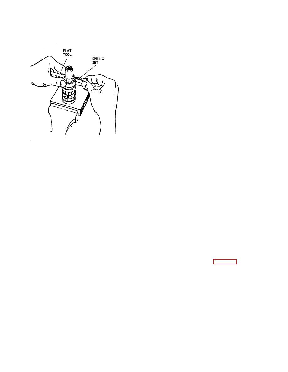
Figure 9-4. Install centering spring set. |
|
||
| ||||||||||
|
|
 TM 10-3930-621-34
Caution: Do not pull control assembly
beyond flush position or cross pin (41) will drop into
housing discharge groove.
(16) Turn splined end of control assembly (38),
checking for free rotation.
(17) Install new packing (43) and check plug (44)
in check plug hole. Use steady pressure on plug and
rock it slightly so packing feeds in smoothly without
cutting.
(18) Install new packing (40) and seal (24) on
spool (50).
(19) Seat cap locator bushing (39), large outside
diameter up, against spool (50) evenly.
c. Mounting Plate.
(1) Check mounting plate seal grooves for
cleanliness and smooth condition.
(2) Install and smooth down new quad ring shaft
seal (24) and oil seal (16) into mounting plate (17) seal
grooves.
Note: Oil seal (16) lip must face away from unit.
(3) Place the mounting plate subassembly) over
ME 3930-621-35194
the spool shaft and slide it down smoothly in place over
the cap locator bushing (39) so that seals will not be
Figure 9-4. Install centering spring set.
damaged.
(4) Aline the bolt holes in the cover (17) with the
(12) Center spring set (42), alining each spring
tapped holes in the housing (48). Be sure the mounting
so the entire set is flush with upper surface of control
plate rests fairly flush against end of housing assembly
spool and sleeve.
so that the cap locator bushing is not cocked.
(13) Install the cross pin (41) through the spool
(5) Install mounting plate attaching bolts (18) and
and sleeve and push into place until pin is flush or slightly
torque each to 150 inch-pounds. d. End Plate.
below the sleeve diameter at both ends.
(1) Reposition control housing (48) in vise,
(14) Place the housing (48) on a solid surface
clamping the mounting plate with 14-hole surface up.
with the port face down. Install the spool assembly with
(2) Check that control spool and sleeve are flush
the splined end of the spool (50) entering the 14-hole
or slightly below 14-hole surface and that surface is
end of the housing first. Push parts gently into place with
clean.
a slight rotating motion.
(3) Place end plate (22) over control spool and
Caution: Use extreme care so control
sleeve, alining bolt holes in plate with tapped holes in
assembly (38) does not lose alinement when
housing (48).
entering housing (48).
(4) Place rotor ring (21) on assembly and aline
(15) Install control assembly (38) in housing bore until
bolt holes.
flush with 14-hole end of housing.
(5) Place splined end of drive (23) in rotor gear
star so slot at control end of drive is alined with outside
diameter valleys of gear. See figure 9-5.
9-6
|
|
Privacy Statement - Press Release - Copyright Information. - Contact Us |
