 |
|||
|
|
|||
|
|
|||
| ||||||||||
|
|
 TM 10-3930-621-34
(8) Remove oil seal (20) and retainer (19) from
7-2. Axle Shaft
shaft. Discard oil seal.
a. Removal and Disassembly.
b. Cleaning, Inspection, and Repair.
(1) Remove drive wheel (TM 10-3930-621-12).
(1) Clean all parts with cleaning compound, solvent
(2) Remove screws (14, fig. 7-3) and lock washers
(Spec. P-S-661). Dry thoroughly with compressed air.
(15) attaching dust shield (13) and remove shield.
(2) Inspect all parts for excessive wear or damage.
(3) Remove screws (17) and lock washers (18)
(3) Replace oil seal. Replace other worn or
attaching bearing retainer (19).
damaged parts as authorized.
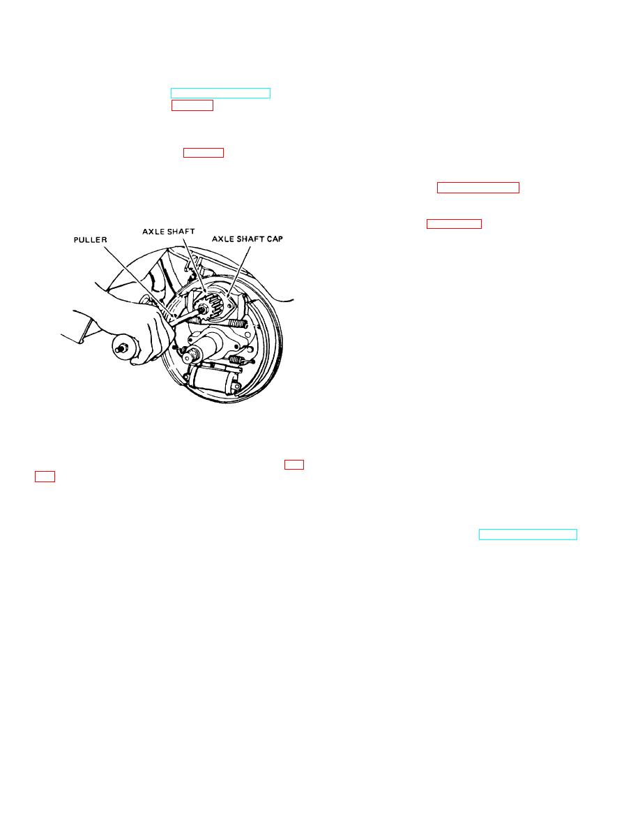
(4) Install threaded puller (fig. 7-2) in threaded end
(4) Grease bearings and shaft pinions (TM 10-
of axle shaft and carefully remove shaft with bearing cap
3930-621-12).
and bearing attached.
(5) Refer to paragraph 1-4 for Repair and
Replacement Standards.
c. Assembly and Installation.
(1) Refer to figure 7-3 and assemble and install
axle shaft as follows:
(2) Slide retainer (19), new oil seal (20), and
greased bearing assembly (21 and 22) on axle shaft (16).
(3) Aline keyed washers (23 and 24) with groove in
shaft (16) and slide into position on shaft.
(4) Tighten nut (25) on shaft until the bearing cup (22)
binds slightly when rotated.
(5) Back nut (25) off one locking position and
secure nut in this position by bending the key of washer
(24) into the slots of nut (25).
(6) To assure that cone assembly (21) backs up to
keyed washer (231, hold bearing cup (22) in a fixed
position and tap the splined end of the axle shaft (16)
with a wooden mallet.
(7) Check cone assembly (21) for free rotation
without drag.
Note. A slight amount of end play (0.005 of an
inch maximum) is permissible.
ME 3930621-35/7-2
(8) Position axle shaft (16) in housing (8) against
Figure 7-2. Pulling axle shaft.
differential. Aline splines and, using a soft mallet, drive
(5) Straighten locking prongs on, key washer (24, fig.
axle shaft splines into differential.
(9) Install retainer (19) to drive housing (8) and
(6) Remove nut (25) and slide washers (23 and 24)
secure with lock washers (18) and screws (17).
from axle shaft (16).
(10) Install dust shield (13) with lock washers (15)
(7) Using suitable press, remove bearing cone
and screws (14).
assembly (21) and cup (22) from shaft.
(11) Install drive wheel (TM 10-3930-621-12).
7-2
|
|
Privacy Statement - Press Release - Copyright Information. - Contact Us |
