 |
|||
|
|
|||
|
Page Title:
Figure 3-37. Battery, installed view |
|
||
| ||||||||||
|
|
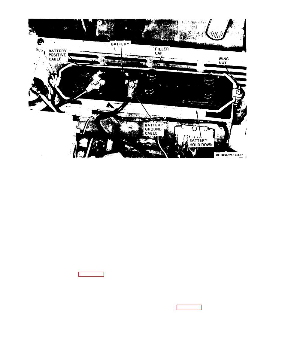 Figure 3-37. Battery, installed view
3-48. Gages, Instruments, and Transmitters
b. Cleaning.
(1) Tighten all filler caps securely. Clean battery
a. General. The gages, instruments, and indicators,
posts, cable terminals, and top of battery with a
are mounted on the instrument panel mounted for-
solution of baking soda and water. Use care to he
ward of the operator's seat. Transmitters to actuate
sure none of solution enters filler caps and gets into
the indicators are mounted on the engine and in the
battery.
fuel tank.
(2) After foaming from solution stops, flush
b. Instrument Removal. Remove instruments by
battery and cable terminals with clean, fresh water.
tagging the wires and disconnecting the wires from
c. Inspection and Testing.
the instrument, removing attaching hardware, and
(1) Check cables for frayed insulation, broken
removing the instrument.
strands, and damaged terminals.
c. Instrument Installation. Install instrument in
(2) Inspect battery for cracks, breaks, and other
proper location, secure with attaching hardware and
defects.
connect wires to instruments.
(3) Use a hydrometer and take a specific gravity
d. Fuses. Fuses are mounted on a fuse holder
reading of the battery. A fully charged battery should
beneath the instrument panel. Remove fuse from
show a reading of 1.265 to 1.290 specific gravity. If
panel and install identical fuse in place. Fuses for
the reading is 1.225 or lower, recharge batter\-.
the hourmeter circuit and stop light circuit are
mounted in holders connected into the wire. Press
battery as follows:
holder and turn one-quarter turn to disengage holder
(1) Lift battery and place in position in batter!
and remove fuse. Install identical fuse in holder and
box with terminals in position shown.
secure holder.
(2) Install hold-down on battery and secure hold-
e. Transmitters.
down to studs with wing nuts, flat washers. and lock
(1) Refer to figure 3-38 and disconnect wire from
washers.
oil pressure transmitter and remove transmitter
(3) Coat battery posts with petroleum jelly (PTA)
from elbow in governor oil line. Install new trans
before connecting cables. Attach cable terminals
mitter and connect wire.
(positive cable first 1 to battery posts.
3-36
|
|
Privacy Statement - Press Release - Copyright Information. - Contact Us |
