 |
|||
|
|
|||
|
|
|||
| ||||||||||
|
|
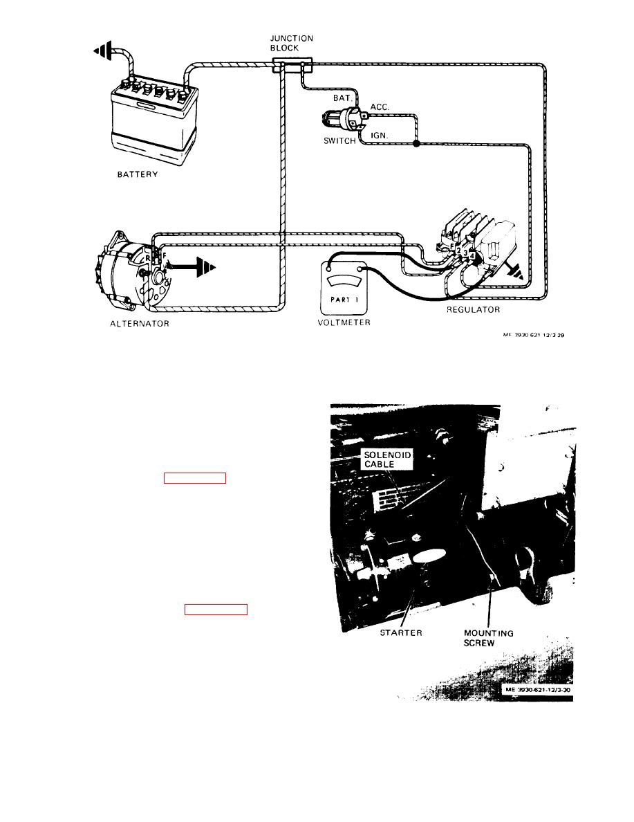
 Figure 3-29. Checking voltage regulator setting.
3-43. Starter and Solenoid
a. General. The starter is mounted to the flywheel
housing on the left side of the engine. Actuation of
the starter is accomplished by depressing the starter
button on the instrument panel.
starter as follows:
(1) Disconnect solenoid cable from terminal on
starter.
(2) Remove two screws and lock washers secur-
ing starter to flywheel housing.
(3) Remove starter slowly from flywheel hous-
ing until pinion gear and drive housing clear open-
ing. Tilt rear of starter up to clear distributor and
water bypass tube and remove starter.
starter as follows:
(1) Tilt starter to clear distributor and water
bypass tube and install pinion gear and drive hous-
ing into opening in flywheel housing.
(2) Mesh pinion gear with flywheel ring gear and
place starter against flywheel housing.
(3) Secure starter to flywheel housing with two
screws and lock washers. Tighten screws securely.
(4) Connect solenoid cable to terminal on starter.
Figure 3-30. Starter, installed view.
3-30
|
|
Privacy Statement - Press Release - Copyright Information. - Contact Us |