 |
|||
|
|
|||
|
Page Title:
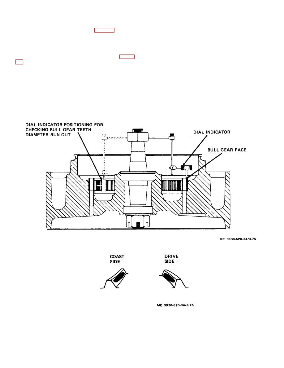
Figure 3-75. Checking bull gear teeth and face runout. |
|
||
| ||||||||||
|
|
 (64) Insure that diameter measures 3.150 +0.003
(71) Separate differential carrier from drive motor
inches T.I.R. (total indicator reading). (fig. 3-77.)
mounting flange.
(65) Check diameter of machined relief in differential
(72) Clean mounting flange.
carrier for the drive motor mounting flange.
(73) Mount a dial indicator on pinion gear face.
(66) Insure that diameter measures between 11.001
(74) Check run-out of mounting flange and insure
and 11.003 inches to pilot drive motor flange onto
that run-out is less than 0.003 inch T.I.R.
differential carrier drive motor mounting flange. (fig. 3-
(75) Check each mounting pad on drive axle and
frame for flatness and squareness.
(67) If diameter of machined relief is less than 11.001
(76) Place a straight bar stock across drive axle pads
inches, drive motor may not mate flush with carrier and
and check for parallelness.
could cause misalignment of pinion and ring gear.
(77) Insure that mounting pads are parallel with each
(68) Relief diameter can be increased to specified
other and on the same horizontal plane.
dimension (11.001 to 11.003 inches) by turning
(78) Repeat steps (75) through (77) for frame
differential on a lathe to remove excess material.
mounting pads.
(69) Check that ring gear mounting screws are
(79) With drive motor removed from lift truck,
tightened.
operate motor with pinion gear attached.
(70) Remove drive motor and drive axle from lift
(80) Check for noise in drive motor or seat brake
truck.
assembly.
Figure 3-75. Checking bull gear teeth and face runout.
Figure 3-76. Proper tooth contact pattern.
3-89
|
|
Privacy Statement - Press Release - Copyright Information. - Contact Us |