 |
|||
|
|
|||
|
|
|||
| ||||||||||
|
|
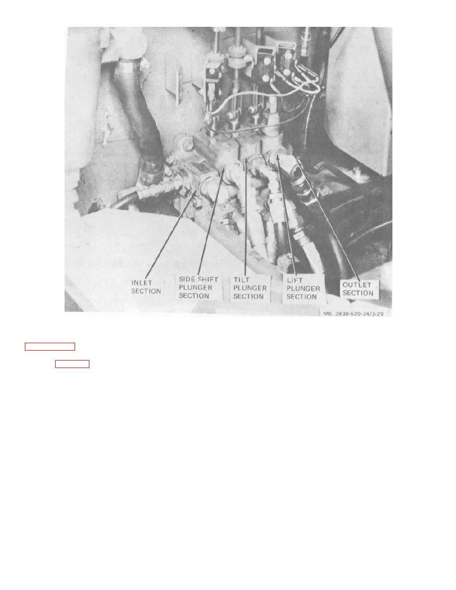
 Figure 3-29. Control valve.
b. Removal. Remove control valve according to
facing downward and tap lightly on plunger section until
poppet slides out.
c. Disassembly. Disassemble control valve as
(7) Remove lift plunger section from tie rods.
(8) Remove seal plate (56) from plunger end
follows: (fig. 3-30.)
of section.
Caution:
Disassembly of hydraulic
(9) Remove plunger cap (51) and seal plate
system components shall be performed in a clean
(56) at opposite end of housing and pull lift plunger from
working area, free of dirt and other foreign matter.
housing.
Note. Position all parts on a flat working
(10) Remove wiper (57) and preformed
surface in order of disassembly, insuring that parts,
packing (58) from lift plunger end of section and identify
which are common between sections, do not become
from which end these were removed.
mixed. Identify and tag all parts.
(11) Remove special screw (54), plunger
(1) Insure that working area is clean and free
spring (55), spring seats (53), and wiper (57) from lift
of dirt and other foreign matter.
plunger.
(2) Position control valve on inlet end.
(12) Remove acorn nut (76), jamnut (75), and
(3) Remove retaining nuts from tie rods (82
copper washers (77) from relief assembly.
and 84).
(13) Turn relief valve assembly out of inlet
(4) Remove outlet section (81) from tie rods.
housing. Flats are provided on cap to remove relief
(5) Remove spring (80), poppet (79), and
valve assembly.
preformed packing (78) from lift plunger section.
(6) If poppet cannot be removed easily, hold
lift plunger section above working surface with poppet
3-46
|
|
Privacy Statement - Press Release - Copyright Information. - Contact Us |