 |
|||
|
|
|||
|
Page Title:
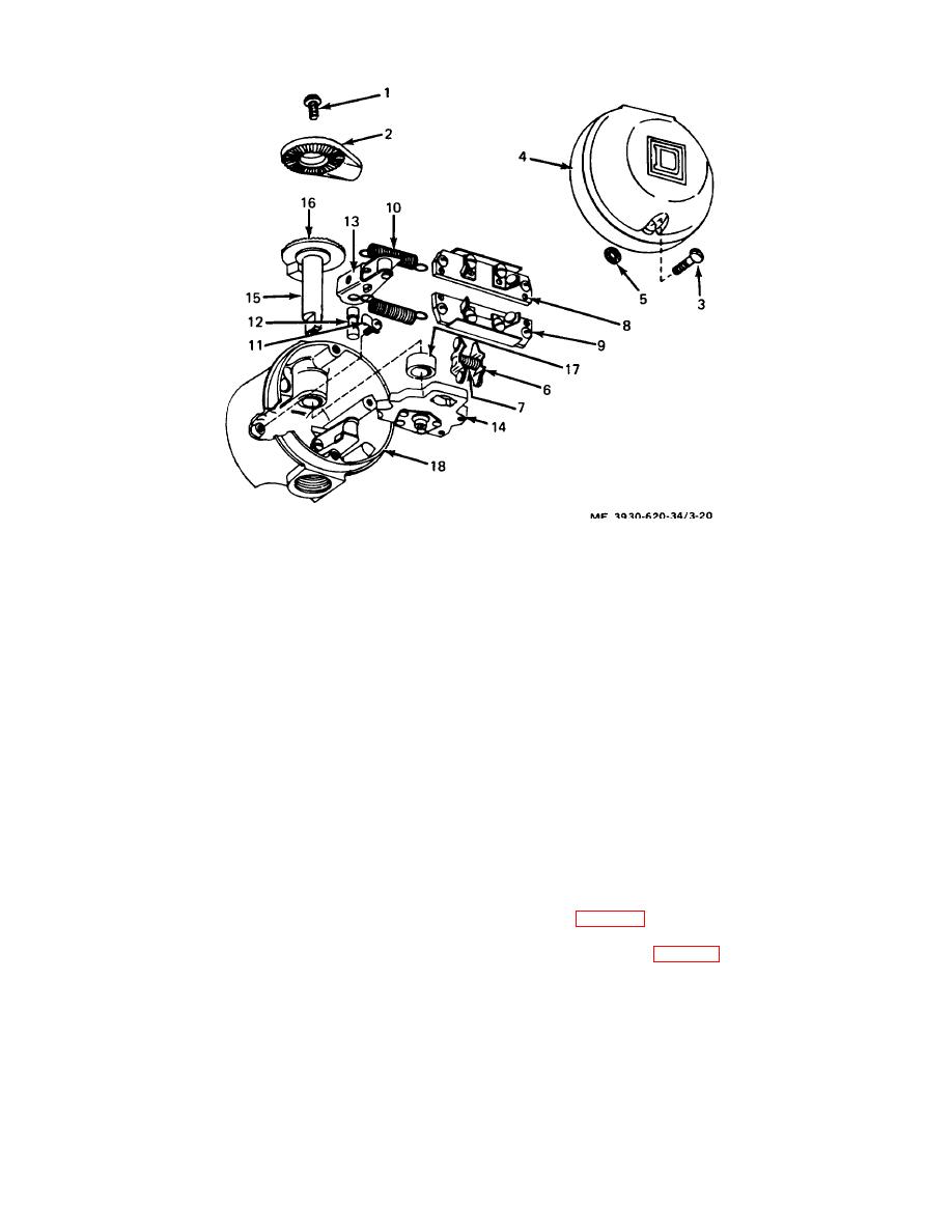
Figure 3-20. Directional control switch. exploded view |
|
||
| ||||||||||
|
|
 1.
Screws
10. Handle spring (2)
2.
Lever end
11. Clip (2)
3.
Screws (2)
12. Hinge pin (2)
4.
Cover
13. Roller arm assembly (2)
5.
Washer (2)
14. Carrier assembly
6.
Contact finger assembly (2)
15. Shaft assembly
7.
Contact finger spring
16. Special washer
8.
Terminal board assembly
17. Spacer
9.
Terminal board assembly
18. Housing assembly
Figure 3-20. Directional control switch.
exploded view.
(2) If additional cleaning is required, wash
(2) Replace all cracked, distorted, or corroded
parts in a dry type solvent and dry with compressed air.
parts.
e. Inspection.
(3) Replace springs if damaged in any way.
(4) Replace terminal boards and contact
(1) Inspect threaded parts and tapped holes
fingers if contacts are pitted or burned.
for stripped threads or other thread damage.
g. Reassembly. Reassemble the switch in the
(2) Inspect cover, housing, lever, arms, clips,
reverse order of disassembly.
carrier, contact fingers, and terminal boards for cracks,
distortion, corrosion, and other damage.
3-13. Thermal Relay
(3) Inspect contacts on terminal boards and
a. Removal.
on contact fingers for pitting, burning and other dam age.
(1) Disconnect
battery
and
discharge
(4) Inspect springs for excessive stretch.
capacitors para 2-5).
f. Repair.
(2) Tag and disconnect the two wires attached
(1) Repair minor thread damage with a tap or
to the thermal relay. (fig. 3-21.)
thread chaser.
(3) Remove the two screws (or nuts), lock
washers, washers, and the clamp.
3-33
|
|
Privacy Statement - Press Release - Copyright Information. - Contact Us |