 |
|||
|
|
|||
|
Page Title:
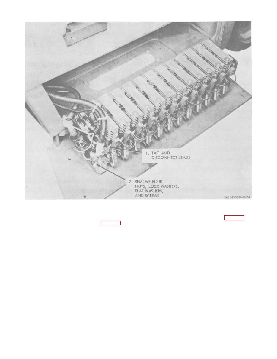
Figure 2-2. Power Assembly removal and installation. |
|
||
| ||||||||||
|
|
 Figure 2-2. Power Assembly removal and installation.
b. Installation.
2-8. Directional Control Switch
(1) Install the switch (9, fig. 2-3) on its
a. Removal.
mounting bracket using the four screws (7) and lock
(1) Remove the roll pin (1, fig. 2-3) and
washers (8).
remove the lever (2).
(2) With the switch cover off, reconnect
(2) Remove the screw (3) and remove the
wiring. Install the switch cover using the two cover
lever end of the switch (4).
screws.
(3) Remove the two screws 15) and lift up the
(3) Position the instrument case cover (6) on
instrument case cover (6).
the case and install the two screws (5).
(4) Remove the directional control switch
(4) Position the lever end (4) on the switch
cover by taking out the two cover screws.
and secure with the screw (3).
(5) Tag and disconnect switch wiring.
(5) Install the lever (2) and secure with the roll
(6) Remove the four screws (7) and lock
pin (1).
washers 18) and remove the switch.
2-5
|
|
Privacy Statement - Press Release - Copyright Information. - Contact Us |