 |
|||
|
|
|||
|
|
|||
| ||||||||||
|
|
 c. Disassembly.
5-15. Wheel Cylinders
(1) Remove nipple (2, fig. 5-17), bleeder
a. Description.
The hydraulic wheel cylinder
screw (1), and elbow (13).
houses two opposed pistons which actuate two opposed
(2) Clamp top end of booster in padded vise.
brakeshoes. Pistons, rubber cups, and springs are held
(3) Carefully unscrew lower part of housing
in the cylinder by pressure from the brakeshoes. Open
from upper part, using a pipe wrench.
ends of the cylinder are protected by rubber boots.
(4) Grasp end of poppet (9) and carefully
b. Removal.
withdraw poppet, sleeve (8), spring (4), and lower cup
(1) Remove brake assemblies (para 5-13).
washer (11) from lower part of housing.
(2) Disconnect brake line at cylinder fitting.
(5) Remove spacer (6), cup washers (7 and
(3) Remove capscrew (8, fig. 5-13) and lock-
11), piston (10), and spring (12) from upper part of
washers (9) and remove cylinder from backing plate (18).
housing.
c. Disassembly.
d. Inspection and Repair.
(1) Remove rubber boots (12) from cylinder
(1) Inspect springs (4) and (2) for distortion or
ends.
stretching.
(2) Push out internal parts.
(2) Check poppet (9), sleeve (8), and piston
d. Cleaning and Inspection.
Use the same
(10) for scratches, burs, and improper sliding fit.
procedures for cleaning and inspection as those used for
(3) Inspect piston bore in upper housing for
the master cylinder (para 5-14). Replace defective parts
scratches or out-of-round condition.
as authorized.
(4) Remove and discard packing (5).
e. Assembly and Installation.
e. Assembly. Reverse procedures in c above.
(1) Reverse procedures in b and c above.
Make sure springs seat properly and no damage occurs
(2) Refer to TM 10-3930-618-20 for bleeding
to housing. Replace packing (5).
of brake system.
f. Installation.
5-16. Brake Pedal
(1) Reverse procedures in b above.
Refer to paragraph 3-17.
(2) Use a suitable thread compound on thread
5-17. Power Booster
connections and make sure connections are tight.
a. Description. The power booster is connected to
(3) Bleed the brake system (TM 10-3930-618-
the master cylinder outlet through a pipe nipple and is
20).
operated by pressure developed by the master cylinder.
The power booster multiplies this pressure and applies
the increased pressure to the wheel cylinders, resulting
in more positive braking.
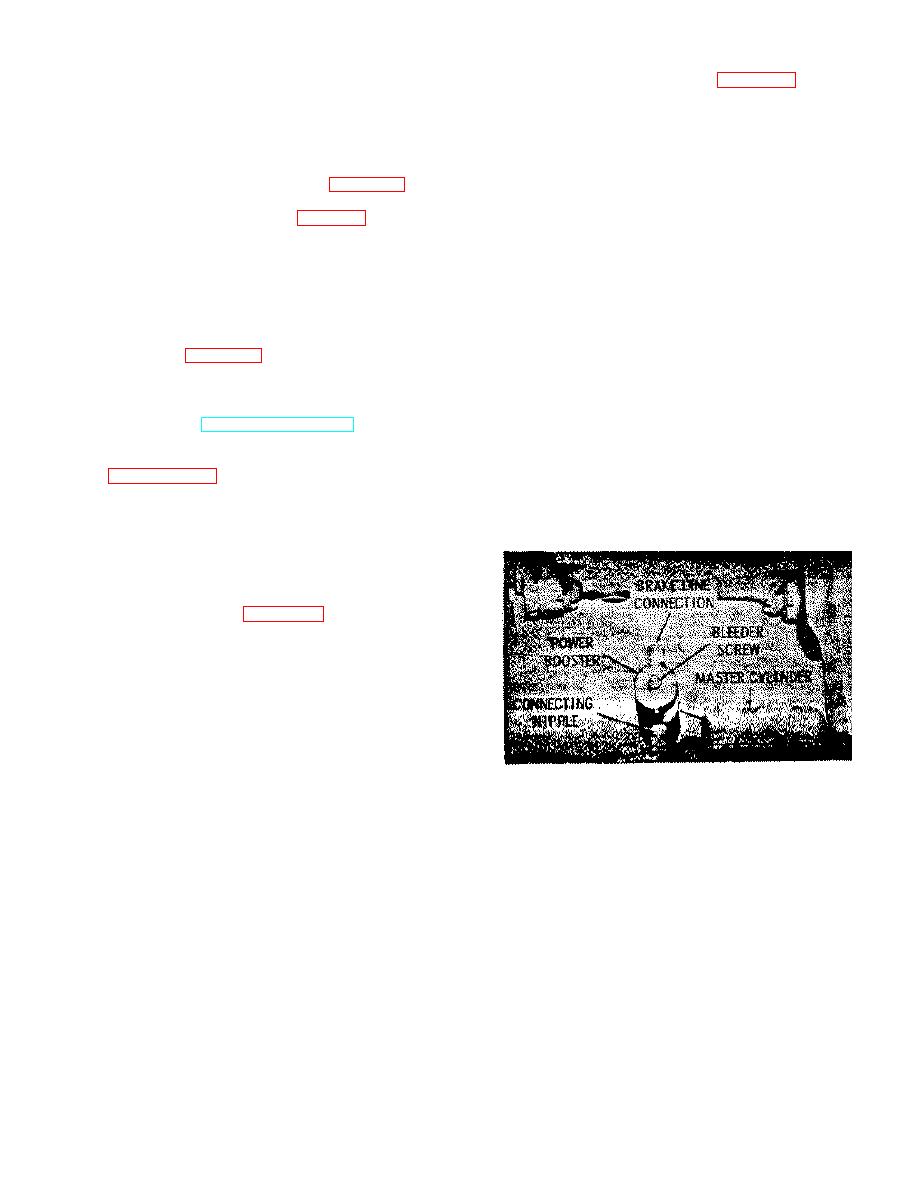
b. Removal. Refer to figure 5-16 and remove the
power booster as follows:
(1) Remove the floor plate.
(2) Disconnect the brake line at the power
booster.
(3) Using an open-end wrench of the proper
size, turn the connecting nipple clockwise, into the
master cylinder, while holding the power booster. The
nipple will turn out of the power booster.
Figure 5-16. Brake power booster, installed valve.
5-21
|
|
Privacy Statement - Press Release - Copyright Information. - Contact Us |