 |
|||
|
|
|||
|
|
|||
| ||||||||||
|
|
 (5) Remove the screws holding the master cylin-
(b) Remove the floor plate and remove the pin
der assembly to the inside of the frame and remove
from the lower cable yoke. Loosen the yoke locknut
the cylinder.
(c) Turn the yoke 3 or 4 turns clockwise to
shorten the cable length.
(d) Install the yoke on the brake lever and
check adjustment by engaging the brake. Readjust as
necessary to prevent the brakeshoes from dragging
when disengaged.
(e) Tighten the yoke locknut and install the
pin.
(f) Install and tighten the setscrew in the
adjusting knob.
2-52. Brake Pedal and Linkage Ad-
justment
The ideal pedal free play is %-inch. Too little free
travel will prevent the master cylinder piston from
returning to full OFF position and the brakes will
begin to drag after several applications. Excessive
free travel will reduce the usable stroke of the master
cylinder. Refer to figure 2-37 and adjust as follows:
a. Remove the floor plates.
b. Slowly depress the brake pedal and check for
1/2-inch free travel. Also observe push rod action.
c. To obtain the proper free travel, loosen the
locknut on the clevis and then turn the adjusting nut.
d. Tighten the locknut and reinstall the floor plates.
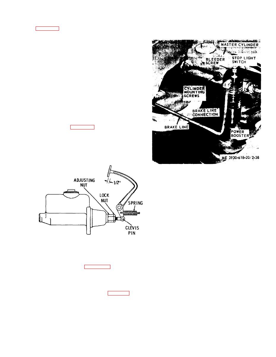
Figure 2-38. Brake master cylinder and brake power booster.
installed view
b. Installation. Reverse procedures in a above. Bleed
the brake hydraulic system as instructed in c below.
c. Bleeding the Brake Hydraulic System. The fluid in
the brake hydraulic system must form a "solid"
column. To do this, the system must be bled of all air
or other gases. Bleeding of the brake system is required
each time the system is drained and refilled with new
fluid ; if some part of the system has been disconnected
for any reason; if the fluid level in the master cylinder
is allowed to decrease to a point where air enters the
system; if the air has entered the system due to a
ME 3930-618-20/2-37
defective master cylinder or wheel cylinders; or if the
brake pedal feels spongy. There is a bleeder screw on
Figure 2-37. Brake pedal adjustment.
each wheel cylinder and on the power booster. To bleed
the system, proceed as follows :
2-53. Brake Master Cylinder
(1) Fill the master cylinder to the proper level
(3/8- to 1/2-in. from the reservoir top).
(2) If a refiller or pressure bleeder is used, place
master cylinder assembly as follows :
the proper adapter in the master cylinder fillercap
(1) Remove the floor plate.
opening and install the refiller or pressure bleeder.
(2) Disconnect the electrical wires at the stop-
(3) Install a bleeder hose on the bleeder screw of
light switch.
either wheel cylinder. Submerge the loose end of the
(3) Remove the power booster (para 2-54).
hose in brake fluid in a glass jar.
(4) Remove the clevis pin holding the pushrod to
(4) Open the bleeder screw one turn.
the brake pedal.
2-43
|
|
Privacy Statement - Press Release - Copyright Information. - Contact Us |
