 |
|||
|
|
|||
|
|
|||
| ||||||||||
|
|
 TM 10-3930-609-35
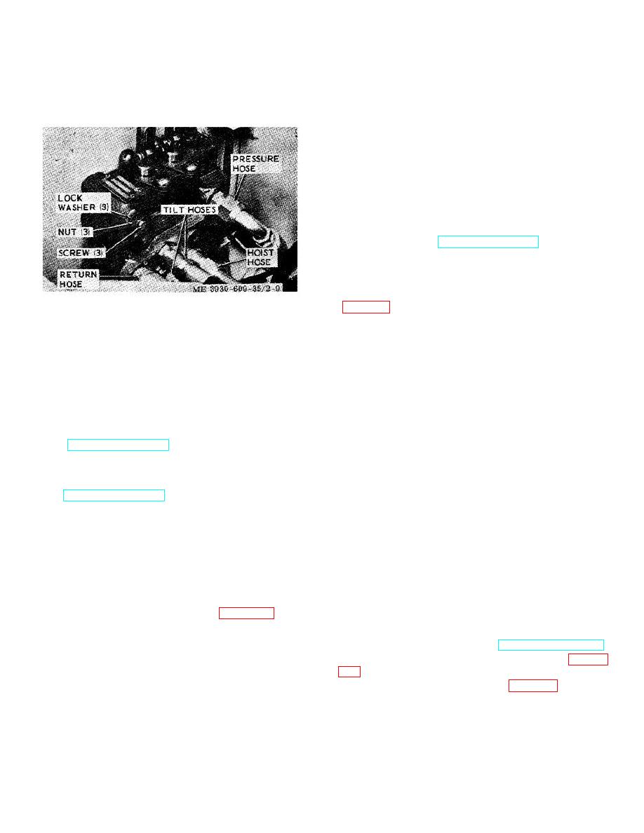
(3) Remove three screws, nuts and
(1) Position hydraulic tank on truck body and
secure with four screws and lockwashers.
lockwashers securing control valve to truck body and
remove control valve.
Screws are removed from
(2) Screw filters on hydraulic tank.
battery compartment side.
(3) Install return -hose to filter fitting and
tighten hose clamp securely.
(4) Install suction hose to bottom of hydraulic
tank and tighten hose clamp securely.
(5) Position seat on hydraulic tank and secure
with hinge pin.
(6) Fill hydraulic tank with oil (LO 10-3930-
609-12) and operate system to check for hydraulic fluid
leakage.
(7) At completion of operational test, install
cowl and floor plate (TM 10-3930-609-12).
2-19. Directional Control Switch
a. Removal.
(1) Remove directional control switch cover
Figure 2-9. Control valve removal.
leads.
(2) Remove return to neutral cable by
b. Installation.
loosening attaching screw.
(1) Install three control valve mounting
(3) Remove four screws securing directional
screws through. truck body from battery compartment
control switch and clamp to steering gear column and
side and mount control valve on screws. Secure with
remove clamp.
removed, nuts and lockwashers.
(4) Unscrew directional control switch off
(2) Reinstall removed hoses according to
conduit coupling and remove from truck.
tags attached at removal. Be certain hoses are tight.
b. Installation.
(3) Attach control valve linkage to control
(1)
Install directional control switch on
valve (TM 10-3930-609-12).
conduit coupling with lever oriented to right of steering
(4) Operate system while gradually increasing
gear column.
loads to check for proper operation and hydraulic fluid
(2) Secure switch to steering gear column
leakage. At completion of operational check-out, install
with clamp and four screws.
cowl (TM 10-3930-609-12).
(3) Secure return to neutral cable to switch
with attaching screw.
2-18. Hydraulic Oil Tank
(4)
With no pressure on operator's seat,
a. Removal.
switch should return to neutral from either the forward or
(1) Drain hydraulic oil from tank (LO 10-3930-
reverse directions.
609-12).
(5)
Reinstall electrical leads to switch
(2) Remove cowl and floor plate (TM 10-
according to tags attached at removal and attach switch
3930-609-12) and pull hinge pin securing seat to
cover.
hydraulic tank.
(3) Loosen hose clamp (fig. 2-10) and
2-20. Steering Gear
disconnect return hose between control valve and filter.
a. Removal.
(4) Loosen hose clamp and disconnect
(1) Remove floor plate (TM 10-3930-609-12).
suction hose at hydraulic tank.
(2) Remove directional control switch (para 2-
(5) Unscrew filters from hydraulic tank.
(6) Remove four screws and lockwashers
(3) Remove two covers (fig. 2-11) mounted
securing hydraulic tank to truck body and lift hydraulic
on steering gear column secured with two screws each
tank from truck.
and disconnect and tag horn leads at connector.
b. Installation.
2-14
|
|
Privacy Statement - Press Release - Copyright Information. - Contact Us |