 |
|||
|
|
|||
|
|
|||
| ||||||||||
|
|
 TM 10-3930-609-12
ME 3930-609-12/3-9
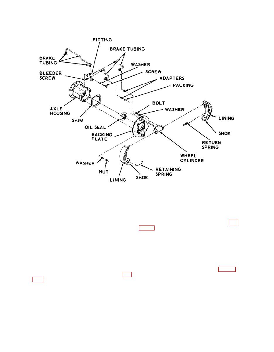
Figure 3-9. Service brake assembly, exploded view.
Section X. ELECTRICAL SYSTEM
3-35. Light Switch
3-33. General
a. Removal.
The electrical system consists of a battery, head-
(1) Remove nut at top of light switch (fig.
light, stop and taillight, resistors, SCR control
panel with magnetic relays, drive motor, pump
panel.
motor and various switches for the operation and
(2) Disconnect, tape, and tag leads from
safety of the fork lift truck. The battery charge
switch.
receptacle is a quick disconnect type so the bat-
b. Installation. Reverse procedures in a above.
tery can be disconnected from the circuit and re-
charged without being removed from the truck.
3-36. Panic Switch
3-34. Hourmeter
a. Removal.
(1) Pull button off panic switch (fig. 2-1),
a. Removal.
unscrew knurled retaining nut at top of switch
(1) Disconnect two leads at hourmeter (fig.
and lower switch out bottom of instrument
panel.
and tag leads for identification.
(2) Disconnect, tape, and tag leads from
(2) Remove two nuts holding hourmeter to
switch.
instrument panel and lift hourmeter off panel.
b. Installation. Reverse procedures in a above.
b. Installation. Reverse procedures in a above.
3-18
|
|
Privacy Statement - Press Release - Copyright Information. - Contact Us |