 |
|||
|
|
|||
|
|
|||
| ||||||||||
|
|
 UPRIGHTS
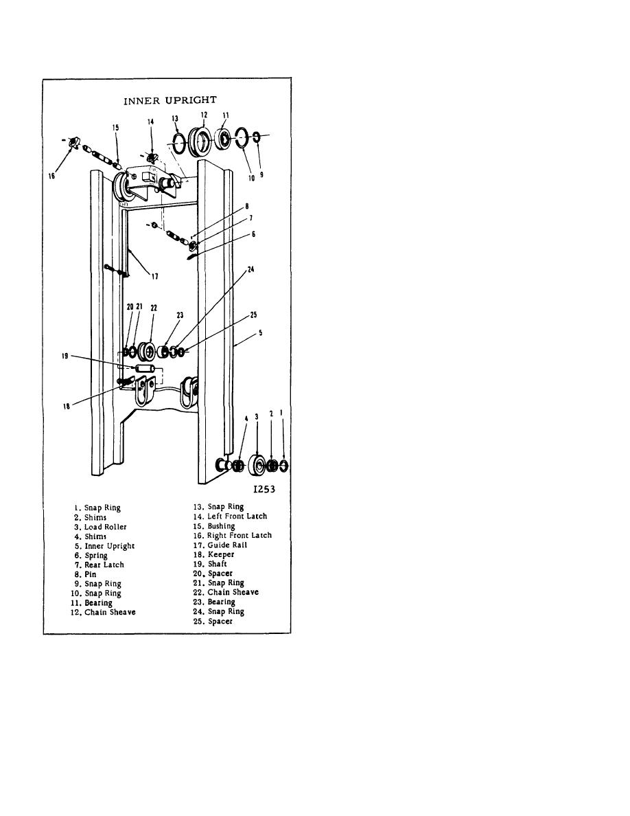
Six chain sheaves provide the necessary rolling
surfaces for the two load chains. The sheaves are ball
bearing equipped and located in the following places:
Two in back of an intermediate crossmember of the
inner upright; one on each side of the crosshead; one on
each side of a box at the top of the inner upright. The
box is welded on the front of the upper crossmember.
The bearings are shielded, lubricated for the life of the
bearing, and replaceable.
One end of each load chain is attached to the back of
the carriage and the other end is attached to a chain
anchor. The bottom ends of the chain anchors are
attached to the cylinder base. Provision for chain
adjustment is at this point.
The bottom crossmember of the outer upright supports
the cylinder. Bolted on top of the support is a shim-
adjusted pad. The pad supports the inner upright when
it is completely lowered. Shims are used to adjust the
relationship between the inner and outer uprights.
A sliding surface between the inner and outer uprights is
provided by strip bearings between the two outer
channels of each of the two assemblies. The strip
bearings are shim adjusted and attached to the top of
the outer upright.
Of the latches, two are behind the upper crossmember
of the inner upright and one is on the front of the box.
Looking from the driver's seat, the right rear latch and
the front latch are splined and pinned to a common
shaft.
Welded to the front of the box is a block and bolted to
the back of the upper crossmember of the carriage is
another block. These are in line with each other and are
called "lifting blocks". Also screwed into the back of the
same crossmember is a lug.
When the inner upright is completely lowered, the right
rear latch is engaged with the outer upright lug, and
Figure 7.
B-172
|
|
Privacy Statement - Press Release - Copyright Information. - Contact Us |