 |
|||
|
|
|||
|
|
|||
| ||||||||||
|
|
 DRIVE AXLE
are on each side of the pinion shaft
through the filler port until it comes out the level port.
bearing carrier in the powershift
Operate the truck a few minutes. Add more oil, if
models. Be sure the pinion bearings
necessary.
are preloaded.
CAUTION:
1. Secure the axle assembly to the transmission
Be sure to re-check the oil level after
using the original gaskets. While the mounting nuts are
a few minutes of operation, since
being tightened, work the ring gear to make sure that
some of the oil will flow into the
backlash is present.
reduction gears.
CAUTION:
Damage to the ring gear or pinion
ADJUSTMENTS
may result if the two are drawn
together
during
the
mounting
A. PINION SHAFT BEARINGS
procedure.
1. The preload of the pinion shaft bearings in the
NOTE:
powershift transmission is not adjustable. If a slight
The ring may be worked back and
preload is not indicated, replace the bearing assembly.
forth with a screw driver inserted in
the filler, check or drain holes.
B. DIFFERENTIAL BEARINGS
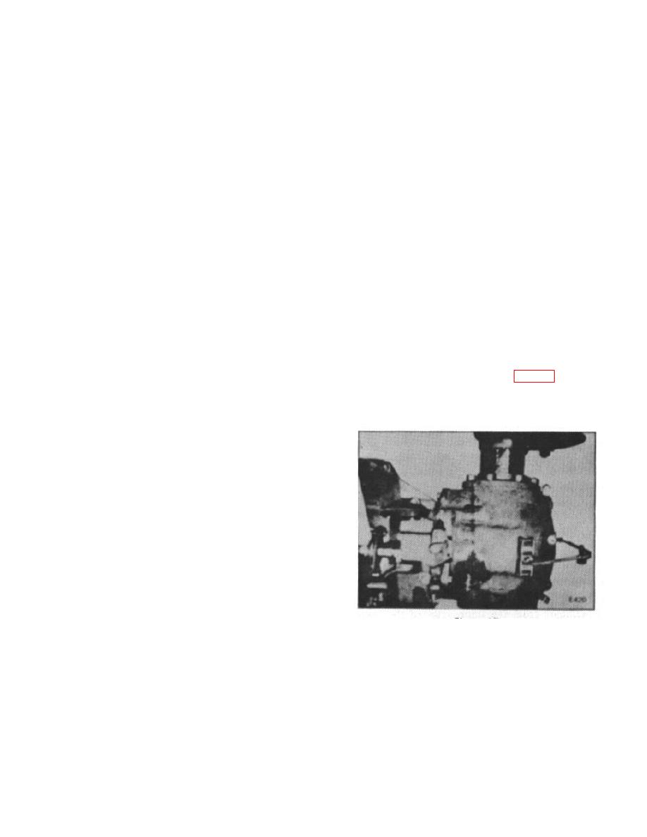
2. Mount a dial indicator on the axle housing with
1. Secure one axle housing to the differential case
the indicator finger inserted into the filler hole and
with a .010 inch gasket between the flanges.
against a tooth on the ring gear. (Fig. 17) The tooth
and the finger should form an angle as close to 90 as
possible.
2. Set the other housing in place and draw the nuts
down until the tapered bearings Just seat in the bearing
cups. At this point there should be no differential
assembly end play nor any preload on the bearings.
3. Make sure the flange surfaces are parallel.
Measure the distances between the flanges with a feeler
gauge. This thickness, less the required preload, will
give the proper number of gaskets or shims necessary
for the axle flanges.
NOTE: The recommended bearing
preload is .005 to .008 inch.
4. Check ring gear for runout. If runout exceeds
.008 inch, remove differential and check for cause.
C. RING GEAR AND PINION
Figure 17.
NOTE:
Correct pinion depth and correct
3. Check the backlash between the ring gear and
backlash between the ring gear and
pinion by working the ring gear back and forth and
pinion are necessary to obtain
noting the indicator reading.
proper tooth contact. The pinion
depth is shim-adjusted. The shims
B-125
|
|
Privacy Statement - Press Release - Copyright Information. - Contact Us |