 |
|||
|
|
|||
|
Page Title:
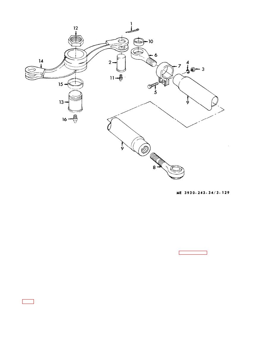
Figure 3-129. Drag link assembly, disassembly and reassembly. |
|
||
| ||||||||||
|
|
 9
Tube assembly
1
Cotter pin
10
packing
2
Pivot pin
11
Fitting
3
Nut
12
Nut
4
Lockwasher
13
Pivot pin
5
Screw
14
Lever assembly
6
Rod end
15
Sleeve
7
Clamp
16
Fitting
8
Rod end
(2) Refer to figure 3-130
and
remove
hydraulic steering cylinders.
a. General. The steering cylinders are mounted to
three of the four wheels of the fork lift. The cylinder
NOTE
t h a t is attached to the right rear wheel is the two
Cap all hydraulic lines after removal.
wheel lock cylinder. Power is supplied to the
c. Recommended Procedure for Repacking all
s t e e r i n g cylinder by the engine mounted hydraulic
Cylinders.
steering pump. The three steering cylinders are
( 1 ) Area the cylinder is to be disassembled in
identical in make. Model RTL10 uses a different
should be as clean as possible to prevent any
c y l i n d e r than Model RTL10-1 as shown in figures
contamination getting into the cylinder or hydraulic
system.
b. Removal.
(2) Pull piston rod out until it bottoms, loosen
(1) Relieve
all
hydraulic
pressure.
|
|
Privacy Statement - Press Release - Copyright Information. - Contact Us |