 |
|||
|
|
|||
|
Page Title:
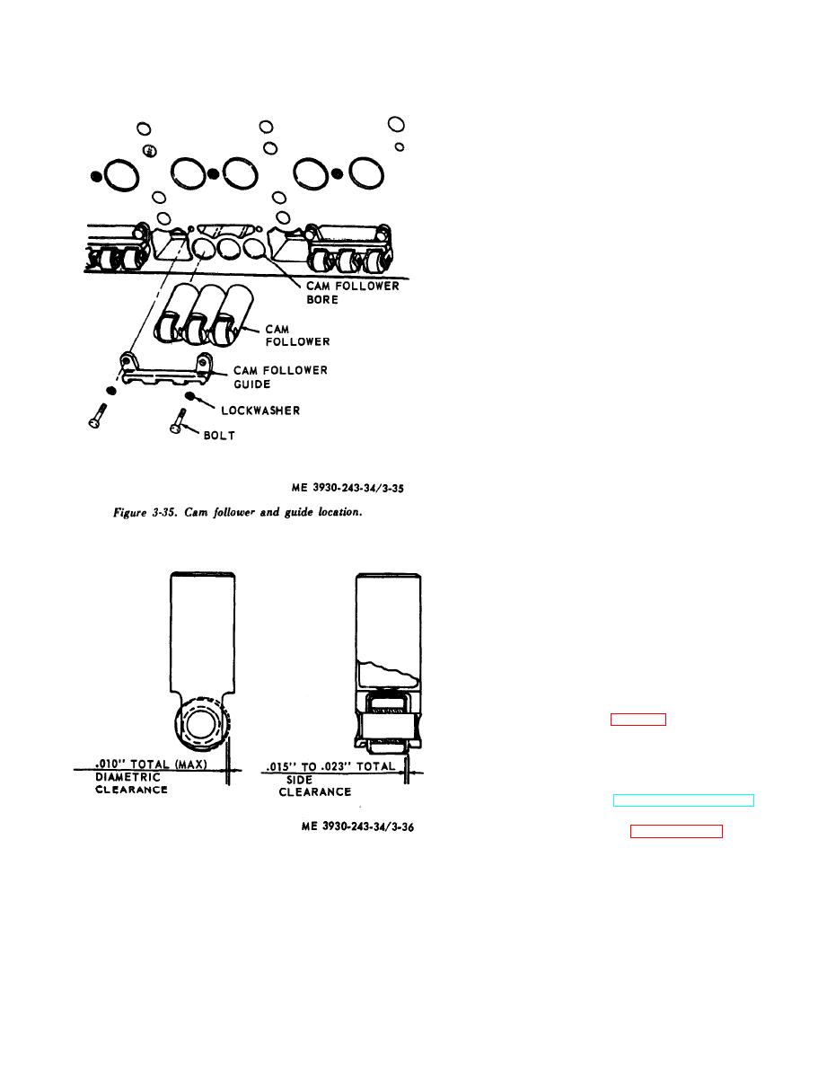
Figure 3-36. Cam roller wear and clearance diagram. |
|
||
| ||||||||||
|
|
 3-16. Fuel Pump
a. General. The fuel pump circulates, or trans-
fers, fuel from the fuel supply tank to fuel i n -
jectors. The pump circulates excess supply of fuel
t h r o u g h the injectors and the unused portion
returns to the fuel tank by means of a fuel return
manifold and fuel return line. The fuel pump is
mounted on the flywheel housing.
b. Fuel Operational Check. If engine operation
indicates an insufficient supply of fuel to the in-
jectors and the fuel level is not low in the supply
tank, check fuel flow between restricted fitting in
the fuel return passage in the cylinder head and the
fuel supply tank as follows:
( 1 ) Disconnect the flexible fuel return tube
from fitting at the fuel tank and hold open end of
pipe in a convenient receptacle.
(2) Start and run the engine at 2500 rpm and
measure the fuel flow return for one minute. Ap-
proximately 0.6 gallon of fuel should flow from the
return tube per minute.
(3) Be sure all pipe connections between the
fuel supply and the pipes are tight so that no air will
be drawn into the fuel system. Immerse the end of
t h e fuel tube in the fuel container. Air bubbles
rising to the surface of the liquid will indicate a leak
on the suction side of the pump.
(4) If the fuel flow is insufficient for
satisfactory engine p e r f o r m a n c e , c h a n g e t h e
element in the fuel strainer and replace the fuel
filter element.
c. Checking Fuel Pump On Equipment. If the
fuel pump fails to function satisfactorily, check for
a broken pump shaft, or dirt in the relief valve
b e f o r e removing the pump from the engine as
follows:
(1) Insert the end of a wire through one of the
pump body drain holes. Crank the engine
momentarily and see if the wire vibrates. Vibration
will be felt if the pump shaft is rotating.
(2) Without removing the pump from engine,
unscrew the valve plug (14, fig. 3-37). Remove the
s p r i n g (16), pin (17) and valve (18). Wash the
p a r t s and blow out the valve cavity with com-
pressed air. Reinstall valve parts.
d. Removal.
(1) Remove fuel pump (TM 10-3930-243-12).
(2) Cap all fuel lines.
disassemble the fuel pump assembly in numerical
sequence.
|
|
Privacy Statement - Press Release - Copyright Information. - Contact Us |