 |
|||
|
|
|||
|
Page Title:
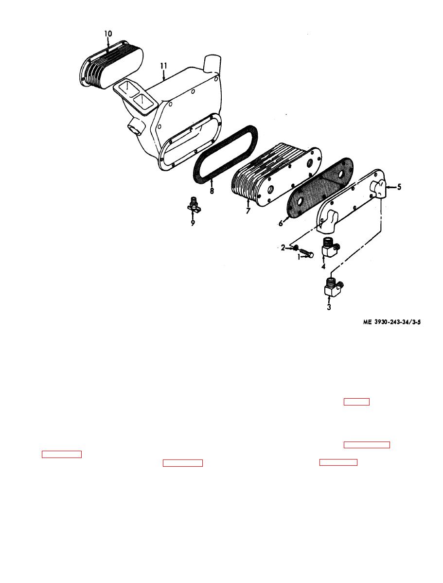
Figure 3-5. Oil cooler, disassembly and reassembly. |
|
||
| ||||||||||
|
|
 1
Screw
7 Core assembly
2
Washer, lock
8 Gasket
3
Elbow
9 Drain cock
4
Elbow
10 Core assembly
5
Cover
11 Housing
6
Gasket
d. Inspection.
3-4. Air Inlet Housing
(1) Inspect the spring (15, fig. 3-7) for bends
a. General. The air inlet housing is mounted to
a n d breaks.
the top of the blower. It contains an air shutdown
(2) Inspect screen (14) for tears.
valve that shuts off the air supply, and stops the
(3) Inspect valves (13) for bends and cracks.
e n g i n e , whenever abnormal operating conditions
Replace a defective part.
requires an emergency shut down.
b. Removal. Remove air intake tube and refer to
reassemble the air inlet housing.
air inlet housing.
d i s s e m b l e the air inlet housing.
|
|
Privacy Statement - Press Release - Copyright Information. - Contact Us |