 |
|||
|
|
|||
|
Page Title:
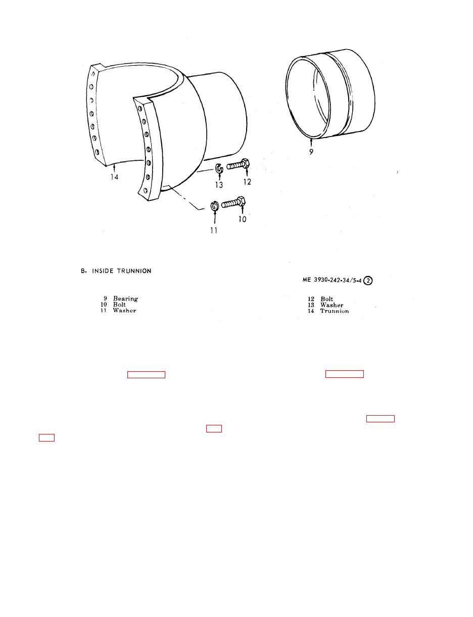
Figure 5-4. Axle assembly, disassembly and reassembly (sheet 2 of 9). |
|
||
| ||||||||||
|
|
 TM 10-3930-242-34
Figure 5-4. Axle assembly, disassembly and reassembly
(sheet 2 of 9).
(4) Remove three screws (8) and remove the
( 4 ) Replace other unserviceable parts with
s e r v i c e a b l e parts.
b a c k i n g plate assembly.
s e m b l e parking brake assembly.
s e m b l e the parking brake.
e. installation.
c. Cleaning and Inspection.
(1) Install the cam lever on the brake link
(1) Clean all parts thoroughly, Use solvent
a n d on the backing plate, Install the brakeshoe
P - D - 6 8 0 , or equal, for cleaning of metal parts.
a s s e m b l i e s and return springs (4, fig. 5-6).
D o not saturate, the brake linings with solvent.
( 2 ) Inspect the parking brakedrum (6, fig.
(2) Install the brakedrum if removed, on the
o u t p u t drive shaft. Install the lockstrip and two
r e t a i n e r bolts. Secure the bolts with the lock-
evident after removing 0.010 inch, replace drum.
strip.
( 3 ) Inspect linings on brakeshoe (3). If lin-
( 3 ) Install the f r o n t p r o p e l l e r s h a f t ( T M
ings are worn to within 1/16 inch of rivet head,
10-3930-242-12).
r e p l a c e linings.
|
|
Privacy Statement - Press Release - Copyright Information. - Contact Us |