 |
|||
|
|
|||
|
|
|||
| ||||||||||
|
|
 TM 10-3930-242-34
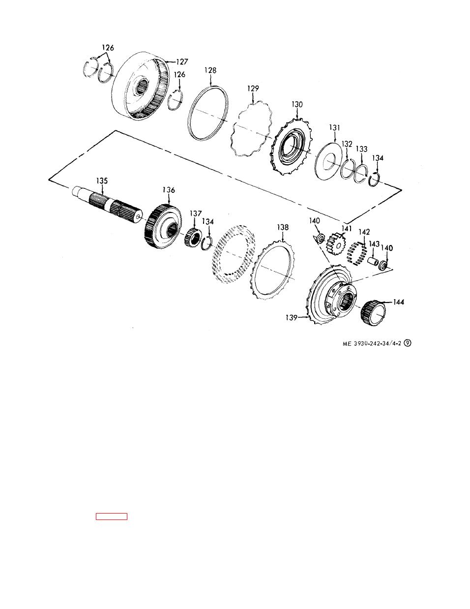
133
Ring
126
Packing
139
Carrier
134
Ring
127
Drum
140
Washer
135
Shaft
128
Seal
141
Pinion
136
Hub
129
Expander
142
Roller
137
Gear
130
Piston
143
Roller
138
Plate
131
Spring
144
Gear
132
Ring
Figure 4-2. Torque converter and transmission assembly,
disassembly and reassembly (sheet 9 of 13).
downward on work bench. Coat the cam pockets
(a) The main pressure may be checked by
of each stator with oil soluble grease.
t h e gage on the instrument panel.
(3) Install eight rollers (21 and 25) into the
(b) The main pressure at full throttle stall
s h a l l o w ends of the cam pockets of each stator
s h o u l d be approximately 110-135 psi.
assembly.
(2) Converter-out-pressure check.
(4) Install eight springs (22 and 26) into the
(a) T h e c o n v e r t e r - o u t - p r e s s u r e m a y b e
deep ends of the cam pockets of each stator as-
c h e c k e d at the point provided for attaching the
sembly.
t e m p e r a t u r e gage sending unit at the upper left
t r a n s m i s s i o n (para 2-6).
s i d e of the converter housing.
h. Pressure Checking.
(b) M a x i m u m c o n v e r t e r - o u t - p r e s s u r e a t
(1) Main pressure check.
f u l l throttle top speed is 65 psi, with transmis-
|
|
Privacy Statement - Press Release - Copyright Information. - Contact Us |