 |
|||
|
|
|||
|
Page Title:
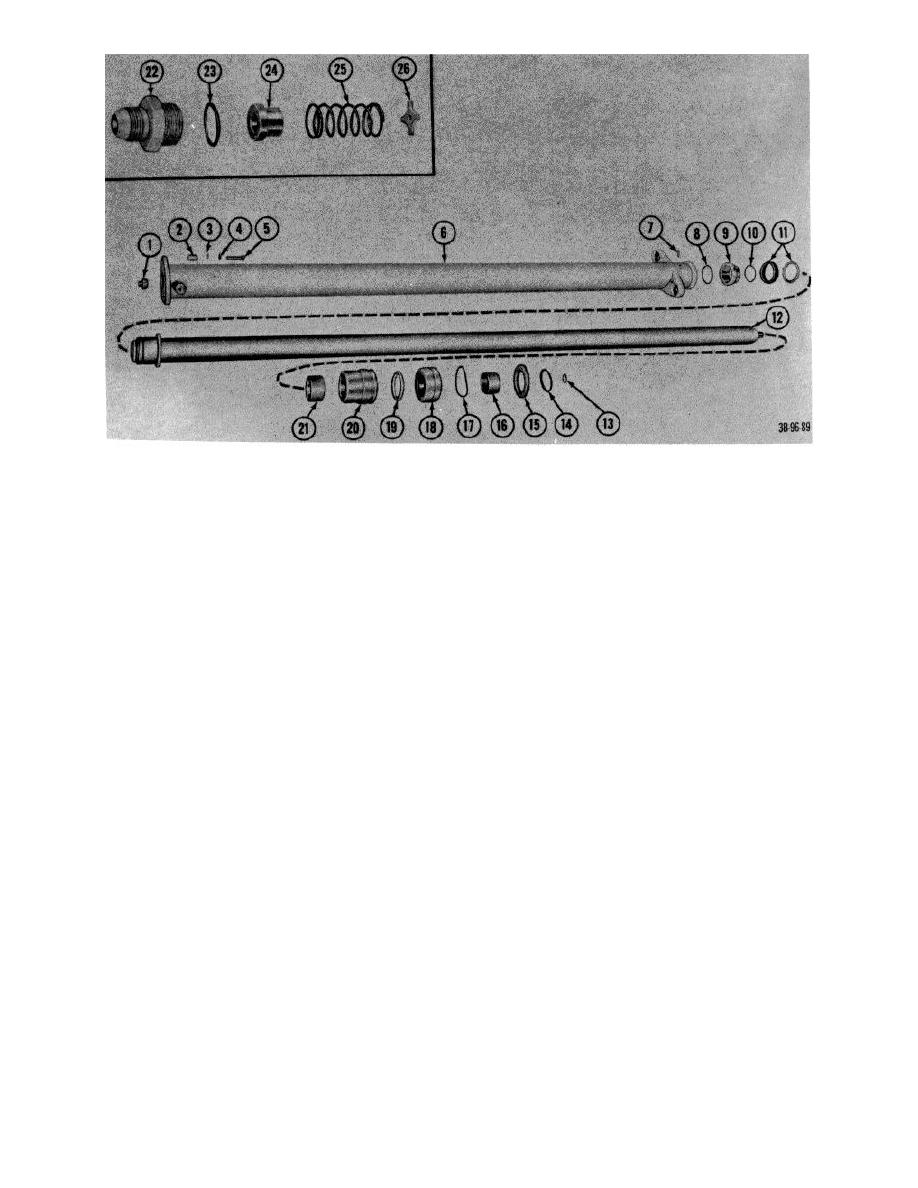
Figure 100. Tilt cylinder, exploded view. |
|
||
| ||||||||||
|
|
 1
End, rod
16
Nut
2
Setscrew
17
Keeper
3
Washer, threaded
18
Lockwasher
4
Ring, wiper
19
Screw
5
Packing
20
Washer, special
6
Retainer
21
Pin
7
Packing, preformed
22
Shell
8
Bushing
23
Washer, special
9
Ring, backup
24
Packing, preformed
10
Packing, preformed
25
Elbow
11
Rod
26
Elbow
12
Piston half
27
Packing, preformed
13
Packing assembly
28
Nut, plain
14
Packing, preformed
29
Setscrew
15
Piston half
30
Fitting, lubrication
Figure 100. Tilt cylinder, exploded view.
(4) Slide plunger (12) from housing (6).
(1) Wash all parts in SD.
(5) Remove packing gland (18) and spacer
(2) Make certain that the adapter (22), spacer
(20) from plunger.
(24), spring (25), and special washer (26)
(6) Remove upper bushing (16), seal (19),
which make up the lowering control valve
and packing (17) from packing gland.
are thoroughly clean.
(7) Remove lower bushing (21) from spacer
(3) Inspect for scored cylinder walls.
(20).
(4) Check housing for cracks and breaks.
(8) Remove retaining ring (8) from bottom of
(5) Inspect piston and plunger for nicks and
plunger.
burs.
(9) Remove lower piston half (9), packing
(6) Replace all defective parts as authorized.
(10) and packing (11) from plunger.
(10) Remove fitting (22) from housing.
d. Assembly.
(11) Remove spacer (24), spring (25), and
(1) Lubricate all parts with hydraulic fluid.
special washer (20) from housing.
(2) Reverse procedures in b above.
(12) Remove packing (23) from fitting (22).
e. Installation
Reverse procedures in a above.
c. Cleaning, Inspection, and Repair.
AGO 7010A
121
|
|
Privacy Statement - Press Release - Copyright Information. - Contact Us |