 |
|||
|
|
|||
|
Page Title:
Figure 82. Carrier assembly showing yoke fitting and pinion shaft. |
|
||
| ||||||||||
|
|
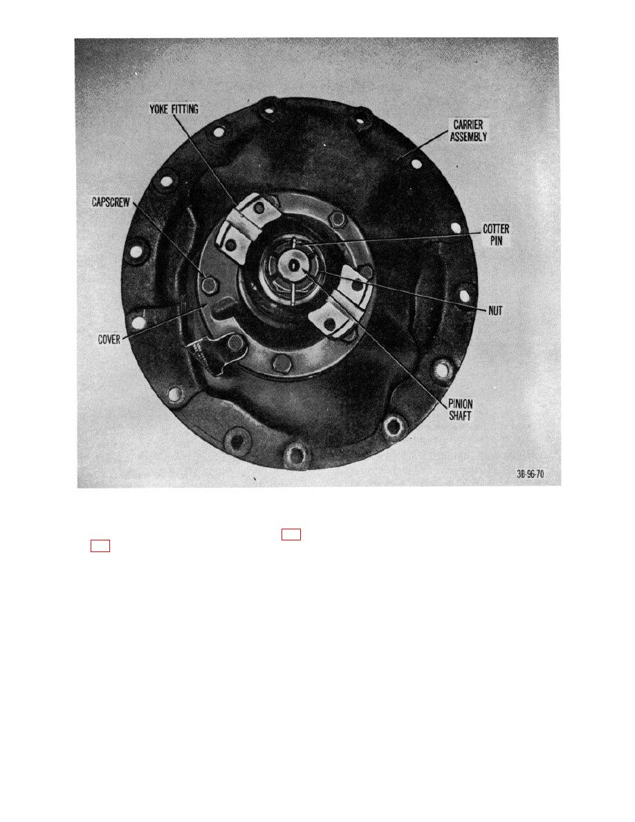 Figure 82. Carrier assembly showing yoke fitting and pinion shaft.
If setting is correct, install lock plate (25, fig.
(7) Rotate the ring gear several times, or until clear
marks of contact between ring gear and pinion
safety wires to secure lock plate capscrews
are obtained.
and carrier capscrews.
Note. The proper mesh is indicated by a
(6) Check the ring gear and pinion for proper mesh
contact area covering approximately 80
by coating approximately six ring gear teeth on
percent of the tooth face, on either side, but
both sides of the high spot with red lead mixed
not reaching either toe or heel, or crest or
with oil.
root of the tooth.
(a) If contact area is confined to the outer
diameter or heel of the ring gear
teeth, move the ring gear toward the
pinion; then add shims to move the
pinion away from the gear to secure
backlash, of 0.006 to 0.012 inch.
AGO 7010A
98
|
|
Privacy Statement - Press Release - Copyright Information. - Contact Us |
