 |
|||
|
|
|||
|
Page Title:
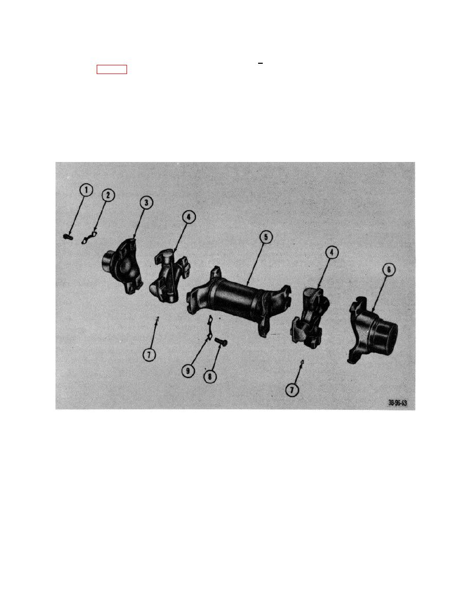
Figure 75. Drive shaft, exploded view. |
|
||
| ||||||||||
|
|
 Section VII. PROPELLER SHAFT (GROUP 09) AND STEERING AXLE (GROUP 10)
c. Assembly and Installation. Reverse procedures
45.
Drive Shaft
in a above.
a. Removal and Disassembly.
(1) screws (1, fig. 76) and lock plates (2) that
46. Steering Axle Assembly
secure shaft (5) to the differential yoke fitting (8)
a. Removal.
and the transmission yoke fitting (6).
(1) Raise rear of truck with a suitable hoist
(2) Remove the shaft and the yokes from the truck.
and place blocks under counterweight and
frame.
(3) Remove screws (8) and lock plates (9) that
(2) Remove steering wheels (TM 108930-
secure universal joints (4) to shaft and separate
222-20).
shaft and bearing assemblies
(3) Place jack under center of steering axle.
b. Inspection Inspect universal joints for wear and
cracks.
1
Screw
6 Fitting, yoke
2
Plate, lock
7 Fitting, lubrication
3
Fitting, yoke
8 Screw
4
Universal joints, cross and bearing assemblies
9 Plate, lock
5
Shaft
Figure 75. Drive shaft, exploded view.
AGO 7010A
89
|
|
Privacy Statement - Press Release - Copyright Information. - Contact Us |
