 |
|||
|
|
|||
|
Page Title:
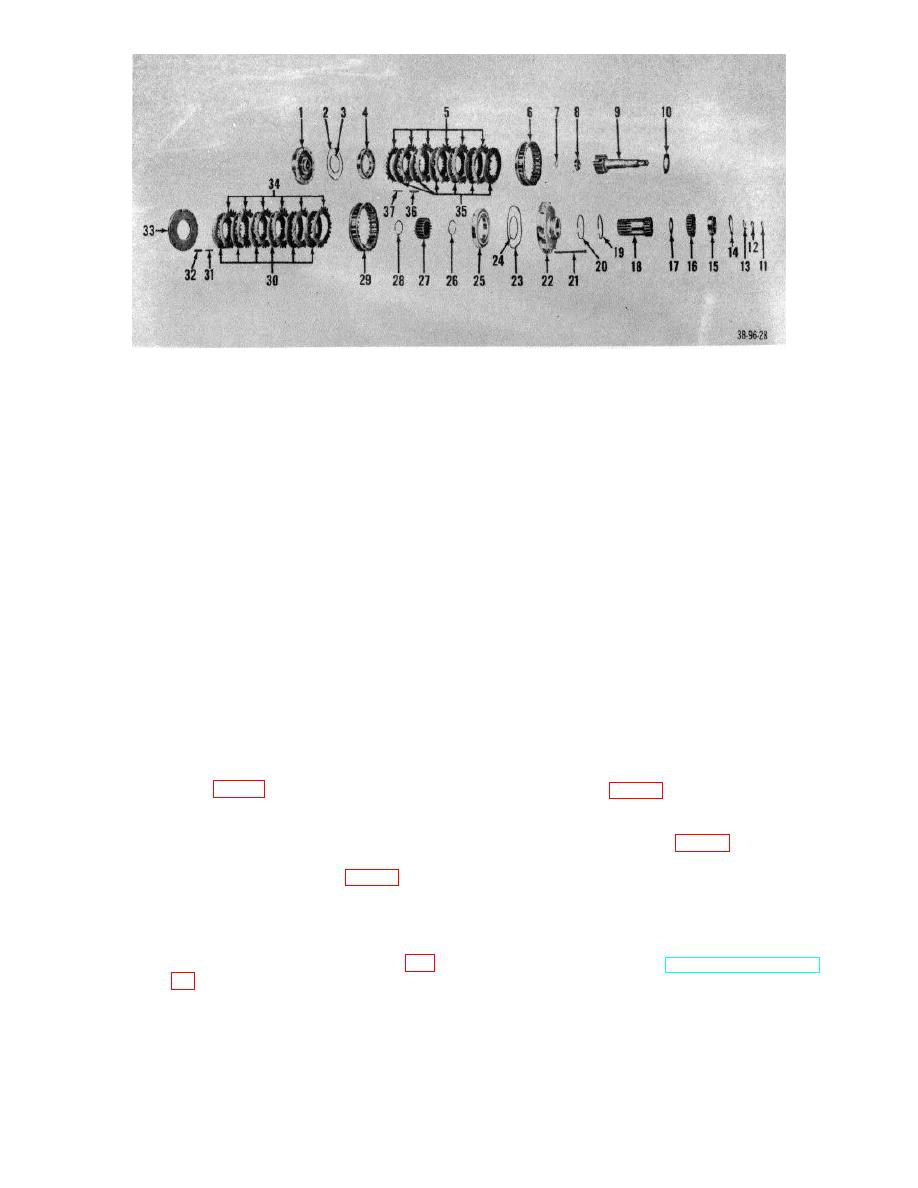
Figure 40. Forward-and-reverse clutch assembly, exploded view. |
|
||
| ||||||||||
|
|
 1
Housing, end
20
Seal, ring, clutch end housing, front
2
Packing, preformed, piston, outer
21
Screw, thru, clutch end housing
3
Packing, preformed, piston, inner
22
Housing assembly, end, front
4
Piston, clutch
23
Packing, preformed, piston, outer
5
Plates, separator, disk
24
Packing, preformed, piston, inner
6
Ring, clutch
25
Piston, clutch
7
Ring, retaining, drive shaft bearing, inner
26
ring, retaining, hub
8
Bearing, ball, annular, drive shaft bearing, inner
27
Hub, clutch
9
Shaft assembly, forward drive
28
ring, retaining, hub
10
Washer, thrust, forward drive gear
29
ring, clutch
11
Seal, ring, shaft, front
30
Disks, friction
12
Seal, ring, shaft, front
31
Spring, retraction, inner
13
Ring, retaining
32
Spring, retraction, outer
14
Ring, retaining
33
Plate, separator ring
15
Bearing, ball, annular, housing end, rear
34
Plates, separator, disk
16
Gear, forward drive
35
Disks, friction
17
Washer, thrust, forward drive
36
Spring, retraction, outer
18
Gear assembly, reverse drive
37
Spring, retraction, inner
19
Seal, ring, clutch end housing, front
Figure 40. Forward-and-reverse clutch assembly, exploded view.
(15) Install and aline eight friction disks
of disk ring before compressing
and seven
separator plates
housing assembly.
alternately beginning with friction
(19) Install seal rings on housing assembly
disks (fig. 64).
Note.
Insure friction disk
(20) Install seal rings on high-and-low
"inner Slot"
clutch hub on opposite side of clutch
(16) Install clutch springs in index of disk
assembly (fig. 67).
ring, making certain that springs eat
e.
Installation.
Reverse procedures in a
on thick separator plate (fig. 64).
above.
(17) Install last separator plate so that lugs
rest on spring (fit. 65).
43. Torque Converter Assembly
(18) Install front end housing on clutch
a. Removal.
assembly.
Compress housing
(1) Remove transmission (par. 38a).
assembly and install thru screws (fig.
(2) Remove starter (TM 10-3930-222 20).
(3) Support engine with suitable blocks.
pounds.
(4) Remove nuts, washers, spacers, star
Caution:
Make certain that top
washer, and pads from rear engine
separator plate is aligned with Index
mount.
AGO 7010A
54
|
|
Privacy Statement - Press Release - Copyright Information. - Contact Us |