 |
|||
|
|
|||
|
Page Title:
Figure 38. Transmission gear assembly exploded view.. |
|
||
| ||||||||||
|
|
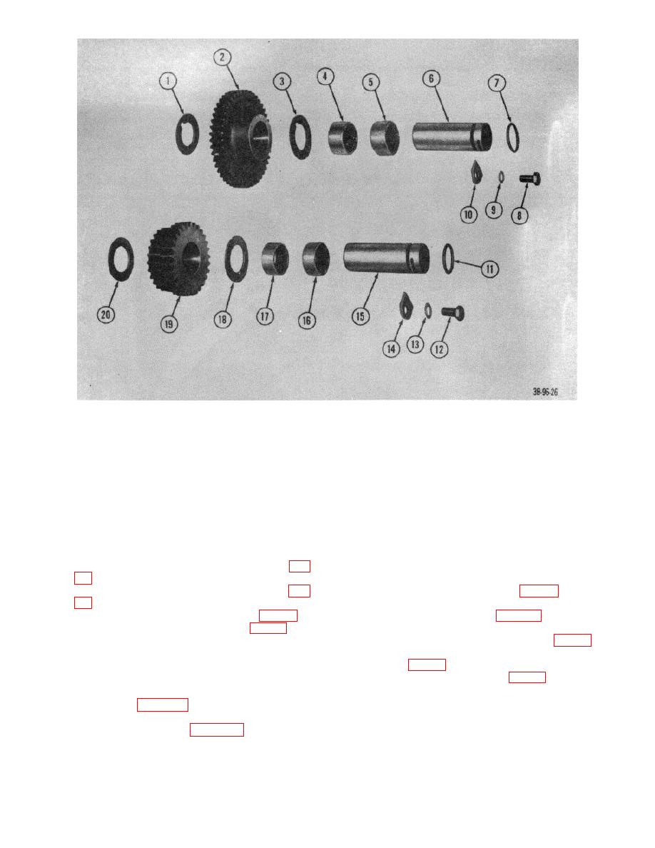 1
Washer, thrust
11
Packing, preformed, cluster gear
2
Gear assembly idler
12
Capscrew
3
Washer, thrust
13
Lockwasher
4
Bearing, roller, needle
14
Keeper
5
Bearing, roller, needle
15
Shaft, cluster gear
6
Shaft, idler gear
16
Bearing, roller, needle
7
Packing, preformed, idler gear shaft
17
Bearing, roller, needle
8
Capscrew
18
Washer, thrust
9
Lockwasher
19
Gear assembly, cluster
10
Keeper
20
Washer, thrust
Figure 38. Transmission gear assembly exploded view..
(5)
Install bearing (12) on rear end housing (fig.
(10) Install friction disk and separator plates
alternately until four disks and four plates are
(6)
Drive high gear clutch hub over bearing (fig.
installed. Aline inner slots (fig. 61) on disks as
they are installed.
(7)
Place clutch ring on rear end housing (fig. 59).
(11) Install thrust washer (fig. 61) on high gear
(8)
Install separator plate in clutch ring (fig. 59).
clutch hub.
(12) Install thick separator plate on hub (fig. 62).
Note.
All separator plates are
(13) Install clutch hub assembly on high gear clutch
"dished". Install all plat
so that
hub (fig. 63).
"dished" side is faced upward. To
(14) Install high gear disk ring (fig. 63) on hub.
check for "dishing" of plates, lay the
plate on smooth surface and use
feeler gage (fig.. 60).
(9) Install outer springs (fig.
59) on lugs of
separator plate.
AGO 7010A
52
|
|
Privacy Statement - Press Release - Copyright Information. - Contact Us |
