 |
|||
|
|
|||
|
Page Title:
Figure 31. Ring gear assembly, removed from transmission. |
|
||
| ||||||||||
|
|
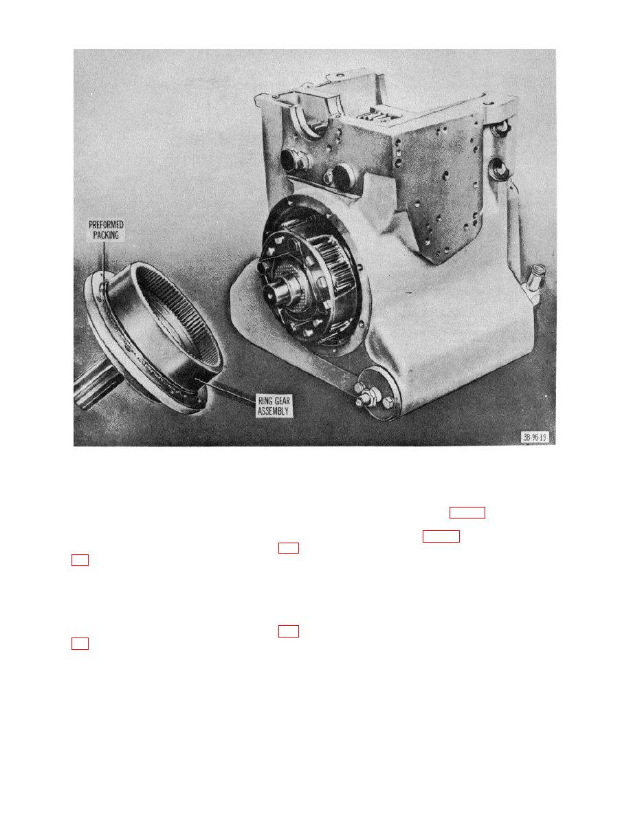 Figure 31. Ring gear assembly, removed from transmission.
(18) Install inner and outer spring assemblies in
teeth on the thrust washer must mesh with the
slots, making certain that springs rest on thick
teeth on the clutch hub.
separator plates (fig. 51).
(14)
Install the forward drive shaft assembly into
(19) Install the sixth separator plate with lugs resting
clutch hub.
on springs (fig. 52).
(15)
Place the thick separator plate on top of the
(20) Place housing end on assemblies.
springs. Be sure capscrew holes are alined (fig.
(21) Press housing end to clutch assembly and
install capscrews and torque capscrews to 15
(16)
Install clutch ring on the thick separator plate.
foot-pounds.
(17)
Install six friction disks and five separator plates
alternately beginning with a friction disk.
Caution: Make certain that top separator
plate is alined with index of clutch ring
must be alined with each other and the blind
before compressing end.
spline on the forward drive shaft assembly (fig.
(22) Install thrust washer on gear assembly with
tangs indexed to gear.
AGO 7010A
45
|
|
Privacy Statement - Press Release - Copyright Information. - Contact Us |
