 |
|||
|
|
|||
|
Page Title:
Figure 24. Generator, exploded view. |
|
||
| ||||||||||
|
|
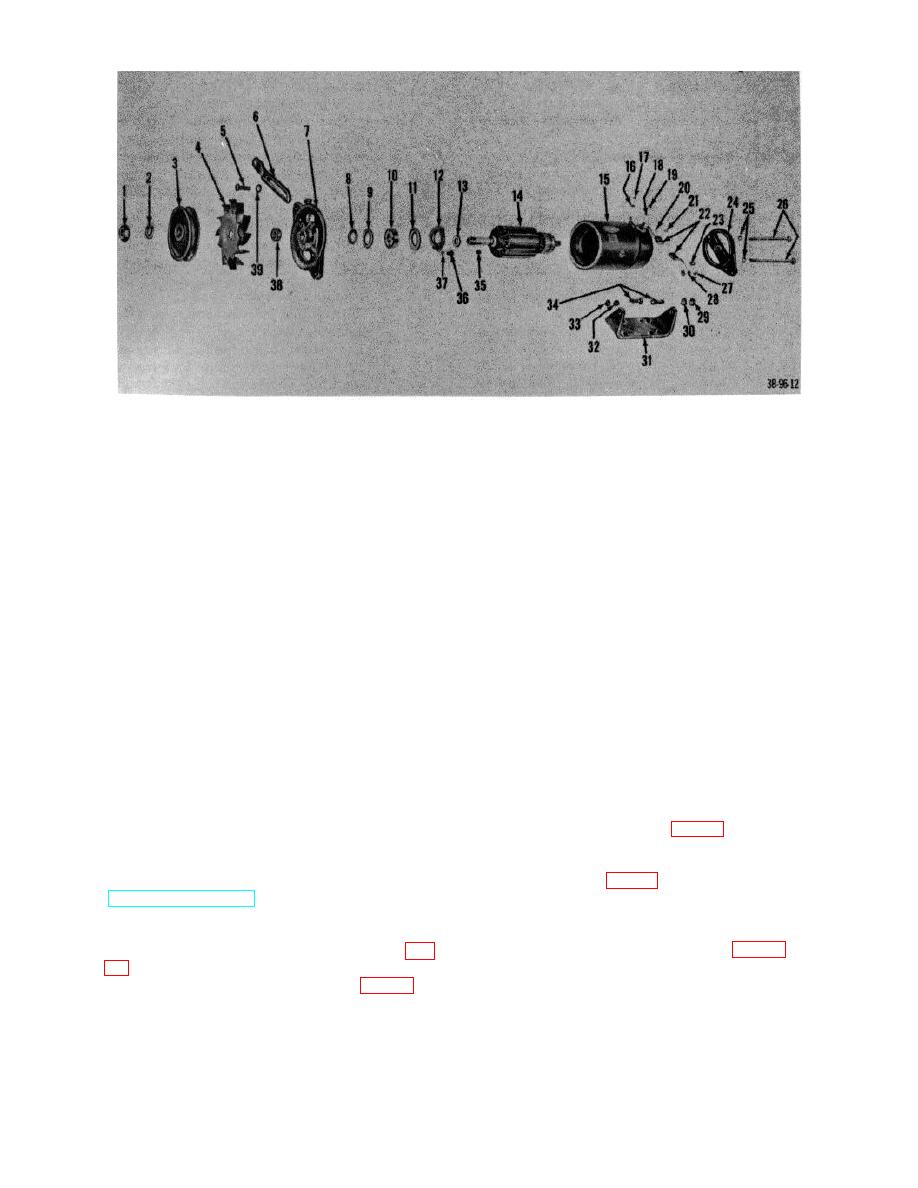 1
Nut, shaft
21
Screw
2
Lockwasher
22
Brush, electrical contact
3
Pulley
23
Spring, brush
4
Fan
24
Frame, commutator end
5
Capscrew
25
6
Plate, generator adjusting
26
Bolts
7
Frame, drive end
27
Screw
8
Washer, felt
28
Lockwasher
9
Plate, felt retaining
29
Nut
10
Bearing, ball
30
Nut
11
Gasket
31
Bracket, generator
12
Plate, bearing retainer
32
Nut
13
Washer, space
33
Nut
14
Armature
34
Bolt
15
Housing
35
Key
16
Lockwasher
36
Screw
17
Nut
37
Washer
18
Lockwasher
38
Collar, space
19
Nut
39
Lockwasher
20
Lockwasher
Figure 24. Generator, exploded view.
Section VI. TRANSMISSION
(7) Disconnect hydraulic hose at the elbow on the
38. Transmission
rear housing cover (fig. 25).
a. Removal.
(8) Remove wiring harness.
(1) Drain transmission.
(9) Remove the retaining nut from the bottom of the
(2) Disconnect drive shaft (par. 45).
taper pin (fig. 25).
(3) Disconnect transmission linkage at control valve
(10)
Fabricate a spacer. Using the
(TM 10-3930-222-20).
fabricated spacer and the nut removed from the
(4) Disconnect inching pedal linkage (TM 10-3930-
taper pin, remove the taper pin from the
222-20).
transmission case top cover (fig. 26).
(5) Disconnect temperature warning transmitter (fig.
(6) Disconnect neutral switch connection (fig. 25).
AGO 7010A
36
|
|
Privacy Statement - Press Release - Copyright Information. - Contact Us |
