 |
|||
|
|
|||
|
Page Title:
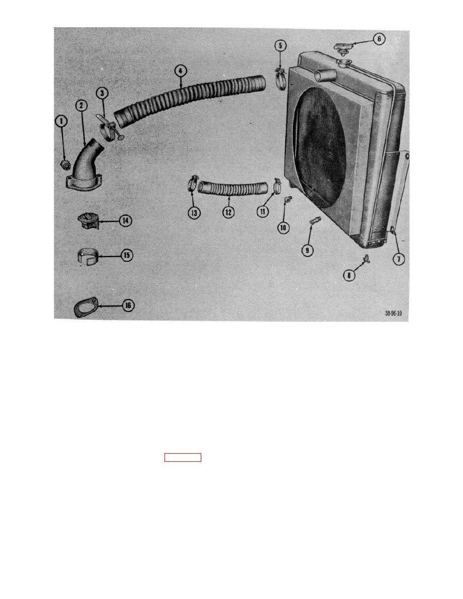
Figure 22. Radiator and attaching parts |
|
||
| ||||||||||
|
|
 1
Fitting
9
Nipple, hose
2
Elbow, cylinder head water outlet
10
Elbow, strut
3
Clamp, ho
11
Clamp, hose
4
Hose, radiator upper
12
Hose, radiator lower
5
Clamp, ho
13
Clamp, hose
6
Cap
14
Thermostat
7
Radiator
15
Ring, thermo adapter
8
Cock, drain
16
Gasket Figure
Figure 22. Radiator and attaching parts
Section V. ELECTRICAL SYSTEM (GROUP 06)
36.
Starting Motor
(38) and remove switch.
a. Removal. Refer to TM 10-4930-222-20.
(3)
Remove plunger return spring (11),
b. Disassembly.
from plunger (10).
(1) Remove screw (16, fig. 23) and
(4)
Remove two bolts (21) that connect
lockwasher (15) that connects the
commutator end frame (20) and drive
solenoid switch (12) to the field
housing (38) to housing (28).
terminal on the starting motor housing
(5)
Remove commutator end frame from
(28).
housing.
(2) Remove screws (14 and 17) and
lockwashers (13 and 27) that secure
AGO 7010A
32
|
|
Privacy Statement - Press Release - Copyright Information. - Contact Us |
