 |
|||
|
|
|||
|
Page Title:
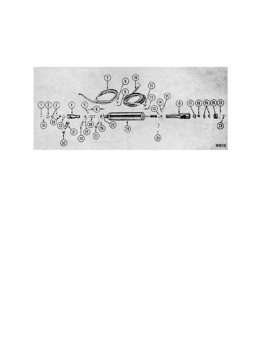
Figure 83. Steering booster cylinder, exploded view. |
|
||
| ||||||||||
|
|
 TM 10-3930-222-20
the center arm assembly.
Pull the rod from the cylinder assembly
and measure half its length.
(5) Check for proper cylinder installation by
noting that the piston "bottoms" at both
(3) Push the rod back into the cylinder to the
ends of the cylinder when the wheels are
measured mark.
in the extreme positions.
(4) Lengthen or shorten the ball socket end
on the rod end until it can be placed on
1
Fitting, lubrication
19
Seat, ball
2
End, plug
20
End, plug
3
Seat, ball
21
Pin, cotter
4
Ball socket assembly
22
Fitting, lubrication
5
Lockwasher
23
Bolt
6
Nuts
24
Cylinder assembly
7
Hose, hydraulic
25
Lockwasher
8
Fitting
26
Clamp
9
Packing, performed
27
Bolt
10
Hose, hydraulic
28
Stud
11
Fitting
29
Clamp
12
Packing, preformed
30
Bolt
13
Clamp
31
Stud, ball
14
Lockwasher
32
Nut
15
Nut
33
Seat
16
Ball socket assembly
34
Spring
17
Seat
35
Pin, cotter
18
Spring
Figure 83. Steering booster cylinder, exploded view.
128
|
|
Privacy Statement - Press Release - Copyright Information. - Contact Us |
