 |
|||
|
|
|||
|
Page Title:
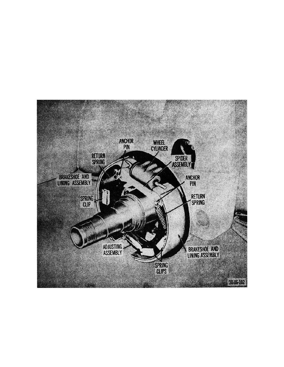
Figure 75. Wheel removed to show service brakes. |
|
||
| ||||||||||
|
|
 TM 10-3930-222-20
(2) Connect a bleeder tube on the bleed
screw on the wheel backing plate and
system will cause a springy, rubbery action of the brake
allow the tube to hang into a container
pedal or will cause the brake pedal to go all the way to
containing hydraulic fluid.
the floor plate under normal pressure. Whenever a line
has been disconnected at the master cylinder, the entire
(3) Depress the brake pedal and open the
system must be bled at both wheels until all air is
bleeder screw. While the brake pedal is
completely expelled.
When a line has been
completely depressed, close the bleeder
disconnected at either wheel cylinder, this cylinder
screw. Release the brake pedal.
together with the cylinder on the opposite wheel must be
(4) Repeat (2) above three or four times, or
bled. Bleed the brakes of air as follows:
until bubbles cease to appear in
(1) Fill the master cylinder with brake fluid.
Figure 75. Wheel removed to show service brakes.
119
|
|
Privacy Statement - Press Release - Copyright Information. - Contact Us |