 |
|||
|
|
|||
|
Page Title:
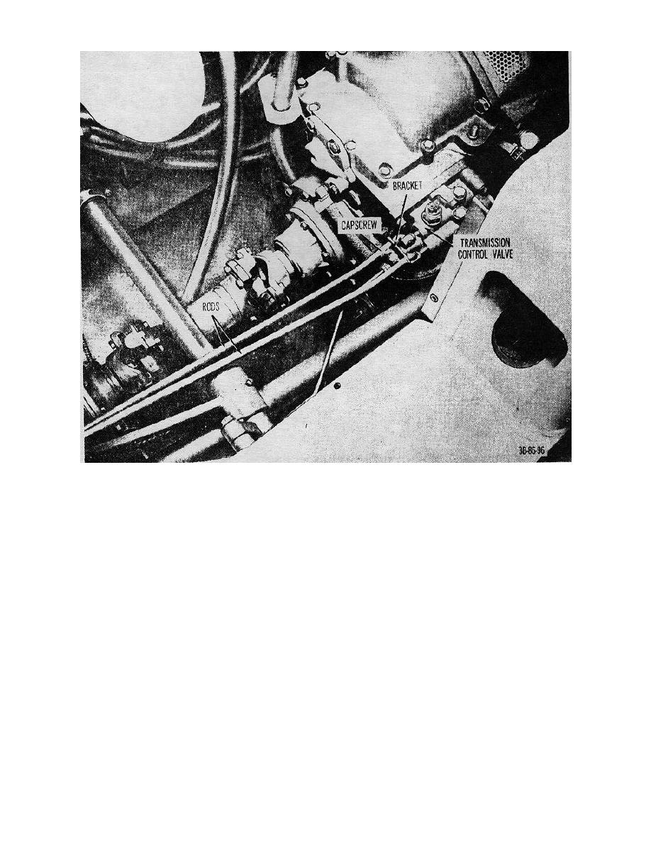
Figure 69. Transmission lever linkage installed on truck. |
|
||
| ||||||||||
|
|
 TM 10-3930-222-20
Figure 69. Transmission lever linkage installed on truck.
Section X. BRAKES (GROUP 12)
the brakeshoe webs. The lower ends of the brakeshoes
61. General
are connected and held against an adjustable link by a
The service brakes are hydraulic and complete braking
helical spring. The adjustable link is an adjusting screw
action is obtainable while traveling in forward or reverse.
threaded into a pivot nut. The outer ends of the
The brakeshoes are full floating and self centering. The
adjusting screw and pivot nut are slotted to provide
brake pedal is mechanically connected to the master
engagement with the web of the brakeshoes. An
cylinder. All brake parts are interchangeable left to
opening is located in the backing plate for brake
right. Each brake has one double piston wheel cylinder
adjustment. The molded brakeshoe linings are bonded
located near the top of the backing plate. The upper
to the brakeshoes.
ends of the two brakeshoes are held against the pistons
and the anchor pin 112 by retracting springs attached to
112
|
|
Privacy Statement - Press Release - Copyright Information. - Contact Us |
