 |
|||
|
|
|||
|
Page Title:
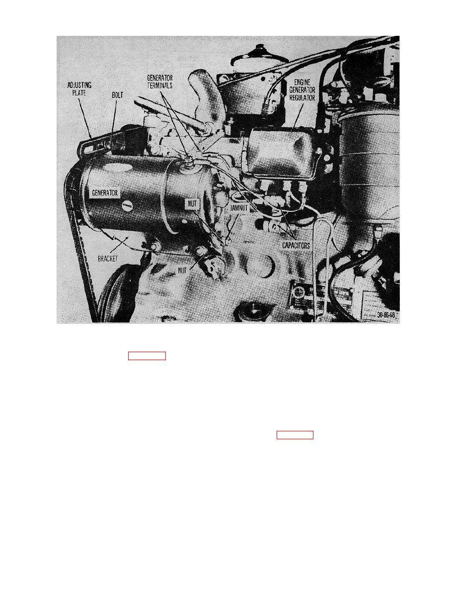
Figure 41. Generator, installed on trock. |
|
||
| ||||||||||
|
|
 TM 10-3930-222-20
Figure 41. Generator, installed on trock.
wrench as shown in figure 48 and turn the
(a) Airgap. The desired airgap setting is 0.075 inch.
adjusting nut to obtain the desired setting. Turn
With the battery disconnected, check the
the nut clockwise to decrease the airgap and
setting. Turn the adjusting nut as shown in
counterclockwise to increase the airgap.
figure 51 to obtain the desired setting. Turn the
nut clockwise to decrease the airgap and
(b) Voltage setting. Hook up test equipment (fig.
counterclockwise to increase the airgap.
49) and check voltage setting for reading of 13.8
to 14.8 volts. Turn adjusting screw as shown in
(b) Current setting. The desired current setting is
figure 50 clockwise to increase the voltage
18.5 to 21.5 amperes. Hook up test equipment
setting and counterclockwise to decrease the
(fig. 52) and turn the adjusting screw as shown
voltage setting.
in figure 53 clockwise to increase the ampere
setting and counterclockwise to decrease the
(3) Current regulator.
The current regulator
ampere setting.
requires an airgap check and current setting as
follows:
82
|
|
Privacy Statement - Press Release - Copyright Information. - Contact Us |