 |
|||
|
|
|||
|
Page Title:
HYDRAULIC JOYSTICK CONTROL VALVE REPAIR |
|
||
| ||||||||||
|
|
 TM 10-3930-673-34
16
This Task Covers:
a. Disassembly
c. Inspection
b. Cleaning
d. Assembly
INITIAL SETUP
Materials/Parts
Tools and Special Tools
Compound, Sealing (Item 42, Appendix B)
Tool Kit, General Mechanic's: Automotive
Grease, Automotive and Artillery
(Item 23, Appendix D)
(Item 18, Appendix B)
Shop Equipment, Automotive Maintenance,
Oil, Lubricating, Transmission/Hydraulic
Common No. 2 Less Power
(Item 30, Appendix B)
(Item 17, Appendix D)
Packing, Preformed
Packing, Preformed
Equipment Condition
Packing, Preformed
Hydraulic joystick control valve removed
Ring, Back-up
(TM 10-3930-673-20)
Seal
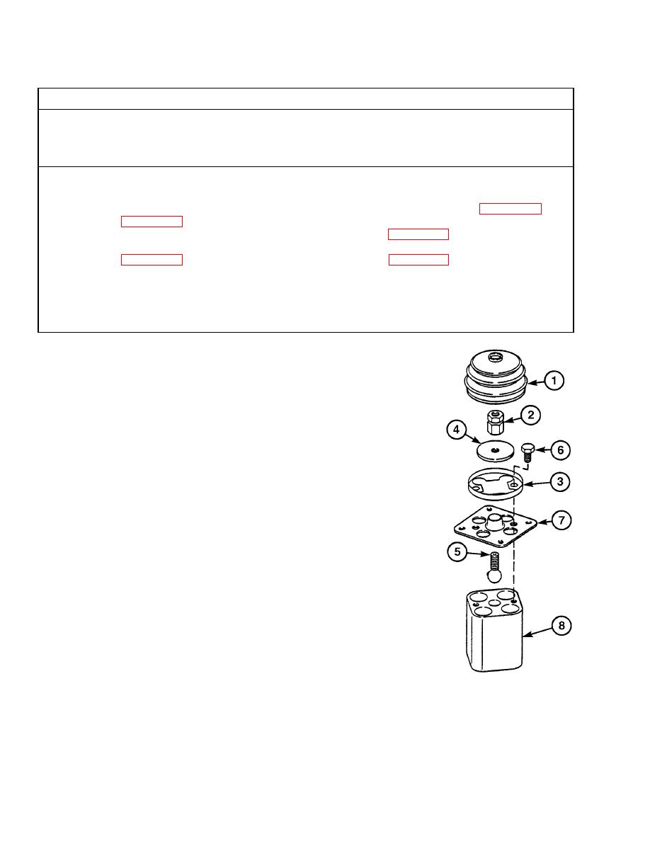
a. Disassembly.
(1)
Remove boot (1) by carefully prying
it from groove in nut (2) and out
from under clamp (3).
(2)
Remove nut (2) and plate (4) from
ball joint (5).
NOTE
Plunger capsules are under spring
compression. Hold plate down and
remove screws in even increments.
(3)
Remove two screws (6), clamp (3),
plate (7), and ball joint (5) from
housing (8).
(4)
Remove ball joint (5) from plate (7).
TR01768
|
|
Privacy Statement - Press Release - Copyright Information. - Contact Us |
