 |
|||
|
|
|||
|
Page Title:
Figure 4-47. Filing Contact Points |
|
||
| ||||||||||
|
|
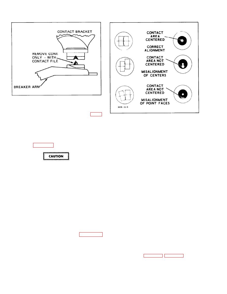 Figure 4-47. Filing Contact Points
crater will form in the negative contact. See figure
4-46.
Figure 4-48. Breaker Point Alignment
e. For a temporary repair, dress the contact
c. After the breaker points have been properly
points with a few even strokes using a clean
aligned, adjust the breaker point gap or dwell.
fine-cut contact file. Do not attempt to remove all
roughness or dress the point surfaces down
4-48. POINT GAP ADJUSTMENT. A scope, a
smooth. See figure 4-47.
dwell meter, or a feeler gauge can be used to check
the gap of new breaker points. A scope or a dwell
meter can be used to check the gap of used breaker
points. Due to the roughness of used points, it is
not advisable to use a feeler gauge to check the
Never use emery cloth or sandpaper to
clean points as particles will be imbedded
gap*
in the points and cause arcing and rapid
a. Remove distributor cap and check and correct
burning.
point alignment, if necessary.
4-47. BREAKER POINT ALIGNMENT. The
b. Rotate the distributor until the rubbing block
b r e a k e r points must be accurately aligned and
rests on the peak of a cam lobe.
strike squarely in order to realize the full
a d v a n t a g e s provided by this design and assure
normal breaker point life. Any misalignment of the
c. If the distributor is in the engine, place the
breaker point surfaces will cause premature wear,
rubbing block on the peak of the cam by
overheating and pitting.
proceeding as follows:
a. Turn the cam so that the breaker points are
d. With the ignition switch off, crank the engine
closed and check the alignment of the points.
by using an auxiliary starter switch between the S
Contact area should be centered. See figure 4-48.
and battery terminals of the starter relay.
b . Align the breaker points to make full face
e. Insert the correct blade of a clean feeler gauge
contact by bending the stationary breaker point
between the breaker points. ( F o r p o i n t s o p e n i n g
bracket. Do not bend the breaker arm.
S p e c . Refer
to
4-36
|
|
Privacy Statement - Press Release - Copyright Information. - Contact Us |
