 |
|||
|
|
|||
|
|
|||
| ||||||||||
|
|
 TM 10-3930-644-14&P
C. INSTALLATION
1. Install self-aligning ball bushings into axle
mounting housings. Screw lubrication fittings
into axle mounting housings.
2. Slide axle mounting housings and spacers on
each end of steer axle.
3. Install tie rods ad tighten adjusting plugs. Pull
adjusting plugs up tight, then loosen so there is
so end play and secure in position with cotter
pins.
4. Attach ball sockets in tie rods and lock in place
with check nuts. Install ball sockets in spindles
and secure with nuts making sure to lock nuts
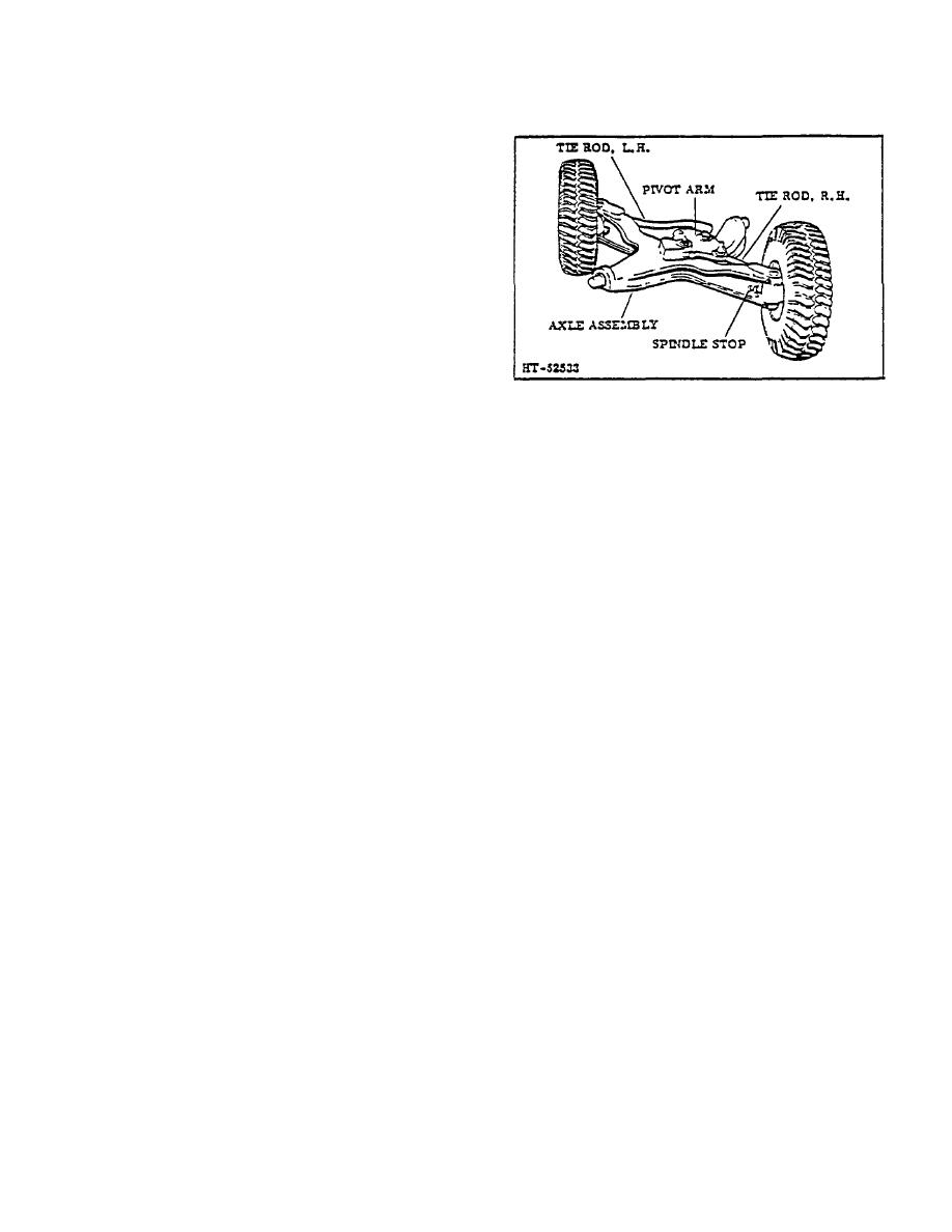
Figure 4. Stop Adjustment
with cotter pins.
4. Set the steer wheels straight ahead, parallel with
5. With steer axle assembly on jack, raise axle
the side of the truck frame. It may be necessary
assembly into position and secure axle mounting
to adjust the tile rods to obtain this position, as
housings to truck frame with capscrews and
zero degrees toe-in must be maintained at all
locknuts.
times.
6. Install equal amount of shims between frame
5. Position the plunger rod half way out of the
and spacers on each end of steer axle to
power steering cylinder. Loosen the locknut that
eliminate all end play. Secure shims to axle
secures the drag link socket to the plunger rod.
mounting housings with capscrews.
Turn the drag link IN or OUT while holding the
housing mounting capscrews to 125 135 ft. lbs.
power steering plunger rod with a wrench on the
flats near the end of the rod. The drag link
7. Install drag link to pivot arm. (Refer to DRAG
socket must be centered over the steer axle
Link Section.)
pivot arm ball stud while the steer wheels are in
a straight ahead position, parallel with the frame.
8. Install steer wheels. (Refer to WHEEL and TIRE
ASSEMBLY Section.)
6. Connect drag link to pivot arm ball stud. Tighten
adjusting plug in end of drag link and install
D. STEERING SYSTEM ADJUSTMENT
cotter pin. Then tighten lookout to secure drag
Link socket to plunger rod.
If the steering system should require adjustment, follow
the procedure outlined below:
7. Remove the blocks and lower the rear of the lift
truck so the steer wheels rest on the floor.
1. Raise the rear end of the truck so that the steer
wheels clear the floor. Block in position.
8. Stan the engine and check the steering system.
With all adjustments correctly made, the wheel
2. Disconnect the drag Link from the pivot an.
spindles should contact the stop screws on the
axle to prevent the piston from bottoming in the
3. Turn the steer wheels full right and full left.
steering cylinder.
Measure the distance between the wheel and
the axle at both wheels. Clearance should be at
least 1/2". While holding this distance, adjust
the spindle stops to allow approximately. 030"
clearance between the stop and the spindle.
2-81
|
|
Privacy Statement - Press Release - Copyright Information. - Contact Us |
