 |
|||
|
|
|||
|
Page Title:
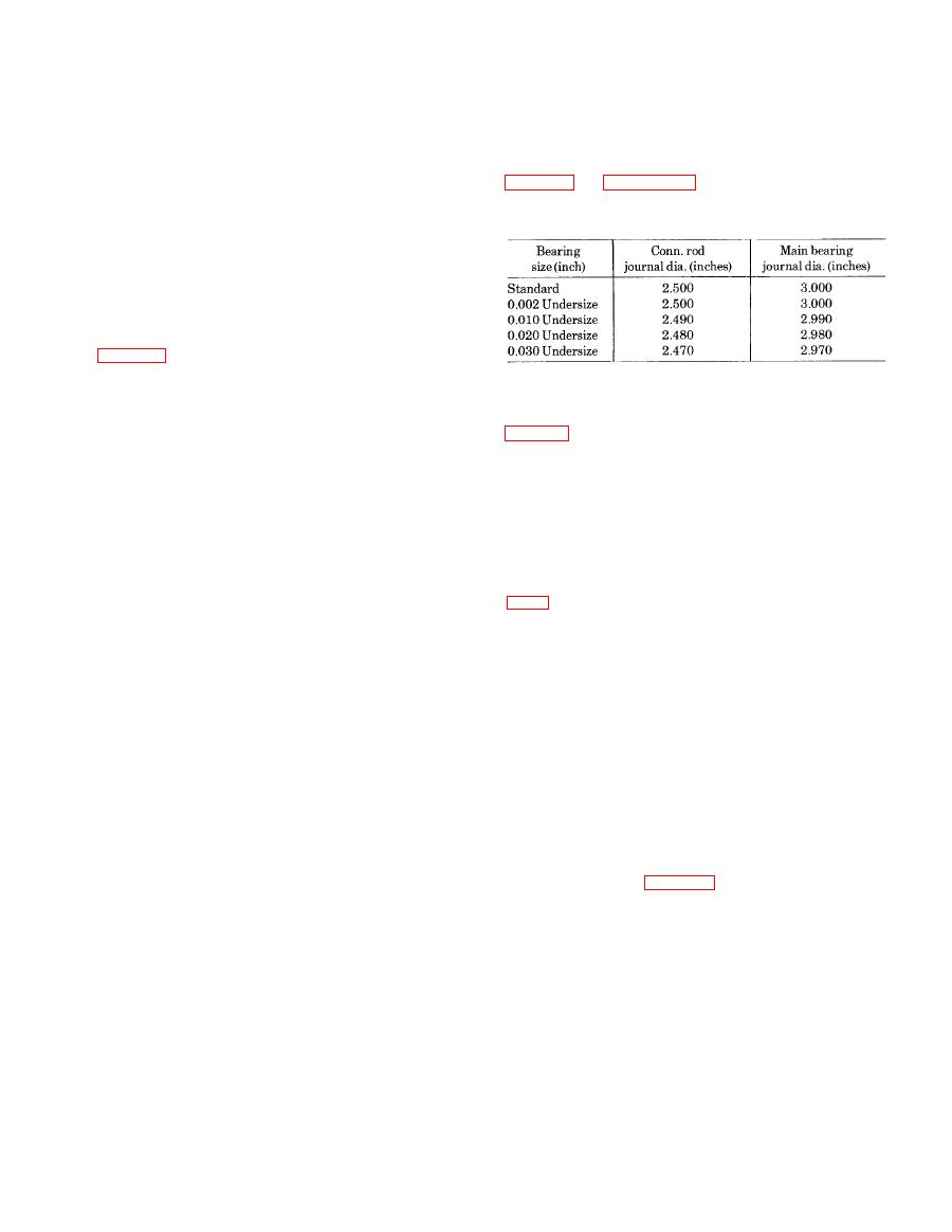
Table 3-2. Crankshaft Dimensions |
|
||
| ||||||||||
|
|
 TM 10-3930-634-34
shafts on which regrinding is unnecessary.
(12) Measure all of the main and connecting rod
(19) If the crankshaft is to be reground, proceed as
bearing journals. Measure the journals at several
follows:
places on the circumference so that taper, out-of-round
(a) Compare the crankshaft journal measure-
and bearing clearances can be determined. If the
ments taken during inspection with the dimensions in
crankshaft is worn so that the maximum connecting
rod journal-to-bearing shell clearance (with new shells)
to which the journals are to be reground.
exceeds 0.0045 inch, or the main bearing journal-to-
bearing shell clearance (with new shells) exceeds
0.0040 inch, the crankshaft must be reground. Also, if
the journal taper or out-of-round is greater than 0.003
inch, the crankshaft must be reground. Measurements
of the crankshaft should be accurate to the nearest
0.002 inch.
(13) Carefully check the crankshaft for cracks
journal surface at an angle of 45 to the axis. Any
(b) Measurement of the crankshaft journals,
crankshaft with such cracks must be rejected. Several
and comparison of these measurements to the diam-
methods of determining the presence of minute cracks
eters required for various undersize bearings shown in
not visible to the eye are outlined below.
(14) Magnetic particle method: The part is magne-
shaft journals must be reground.
tized and then covered with a fine magnetic powder or
(c) If one or more main or connecting rod jour-
solution. Flaws, such as cracks, forma small local mag-
nals require grinding, then grind all of the main jour-
net which causes the magnetic particles in the powder
nals or all of the connecting rod journals to the same
or solution to gather there, effectively marking the
required size.
crack. The crankshaft must be demagnetized after the
(d) All journal fillets must have a 0.130 inch to
test.
0.160 inch radius between the crank cheek and the
(15) Fluorescent magnetic particle method: This
journal and must not have any sharp grind marks (fig.
method is similar to the magnetic particle method, but
is more sensitive since it employs magnetic particles
journal and the crank cheek, and must be free of
which are fluorescent and glow under "black light".
scratches, The radius may be checked with a fillet
Very fine cracks that may be missed under the first
gage.
method, especially on discolored or dark surfaces, will
be disclosed under the "black light".
which often produces grinding cracks. Cool the crank-
(16) Fluorescent penetrant method: This is a
shaft while grinding, using coolant generously. Do not
method which may be used on non-magnetic materials
crowd the grinding wheel into the work.
such as stainless steel, aluminum and plastics. A
(f) Polish the ground surfaces to an 8-12
highly fluorescent liquid penetrant is applied to the
R.M.S. finish. The reground journals will be subject to
part. Then, the excess penetrant is wiped off and the
excessive wear unless polished smooth.
part is dried. A developing power is then applied
(g) If the thrust surfaces of the crankshaft are
which helps to draw the penetrant out of the flaws by
worn or grooved excessively, they must be reground
capillary action. Inspection is carried out under "black
and polished. Care must be taken to leave a 0.130 inch
light".
to 0.160 inch radius between each thrust surface and
(17) A majority of indications revealed by the
the bearing journal (fig. 3-135, E).
above inspection methods are normal and harmless
(h) Stone the edge of all oil holes in the journal
and only in a small percentage of cases is reliability of
surfaces smooth to provide a radius of approximately
3
the part impaired when indications are found. Since
/32 inch.
inspection reveals the harmless indications with the
(i) After grinding has been completed, inspect
same intensity as the harmful ones, detection of the in-
the crankshaft by the magnetic particle method to de-
dications is but a first step in the procedure. Inter-
termine whether cracks have originated due to grind-
pretation of the indications is the most important step.
ing operation.
(18) In addition to the standard size main and
(j) Demagnetize the crankshaft.
connecting rod bearings, 0.002 inch, 0.010 inch, 0.020
(k) Remove the plugs and clean the crankshaft
inch and 0.030 inch undersize bearings are available.
and oil passages thoroughly with fuel oil. Dry the shaft
NOTE
with compressed air and reinstall the plugs.
The 0.002 inch undersize bearings are used
(20) Inspect the shells visually for scoring, pit-
only to compensate for slight wear on crank-
ting, flaking, cracking, loss of babbitt, or signs of over-
3-85
|
|
Privacy Statement - Press Release - Copyright Information. - Contact Us |
