 |
|||
|
|
|||
|
Page Title:
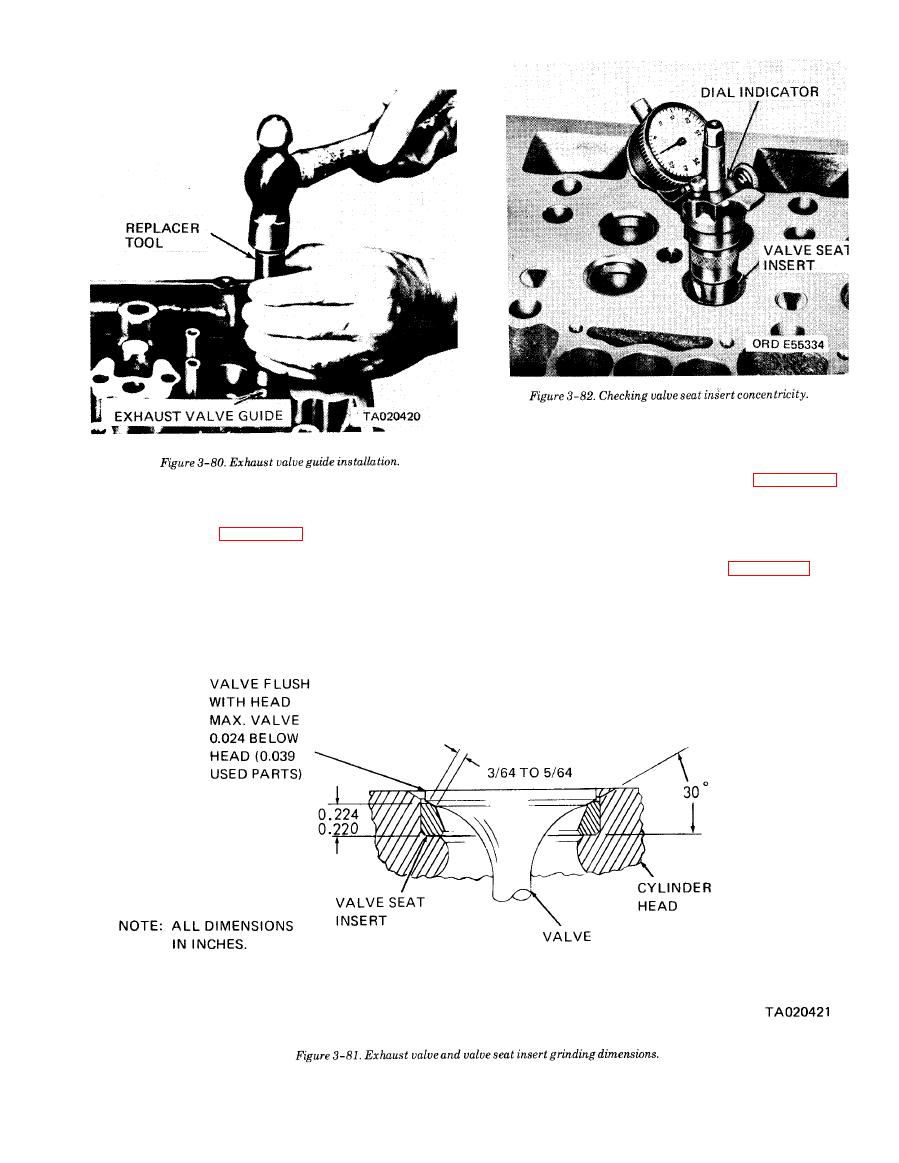
Figure3-80. Exhaust valve guide installation |
|
||
| ||||||||||
|
|
 TM 10-3930-634-34
(f) Grinding will reduce the thickness of the
valve seat insert and cause the valve to recede into the
cylinder head. If, after several grinding operations the
valve recedes beyond the limits shown in figure 3-81,
replace the valve seat insert.
an old insert is reconditioned, the valve inserts must
(g) After grinding has been completed, dean
be ground.
the valve seat thoroughly with cleaning solvent (Fed
Spec P-D-680) and dry with compressed air. Set a dial
insert grinding specifications.
indicator in position as illustrated in figure 3-82, and
CAUTION
rotate the dial indicator to check the concentricity of
Do not allow the grinding wheel to touch the
each valve seat relative to the valve guide. If the run-
cylinder head when grinding the inserts.
out is excessive, check for a bent valve guide before re-
(e) Apply a 30 grinding wheel to the valve seat
grindng the insert.
insert.
|
|
Privacy Statement - Press Release - Copyright Information. - Contact Us |
