 |
|||
|
|
|||
|
|
|||
| ||||||||||
|
|
 TM10-3930-634-34
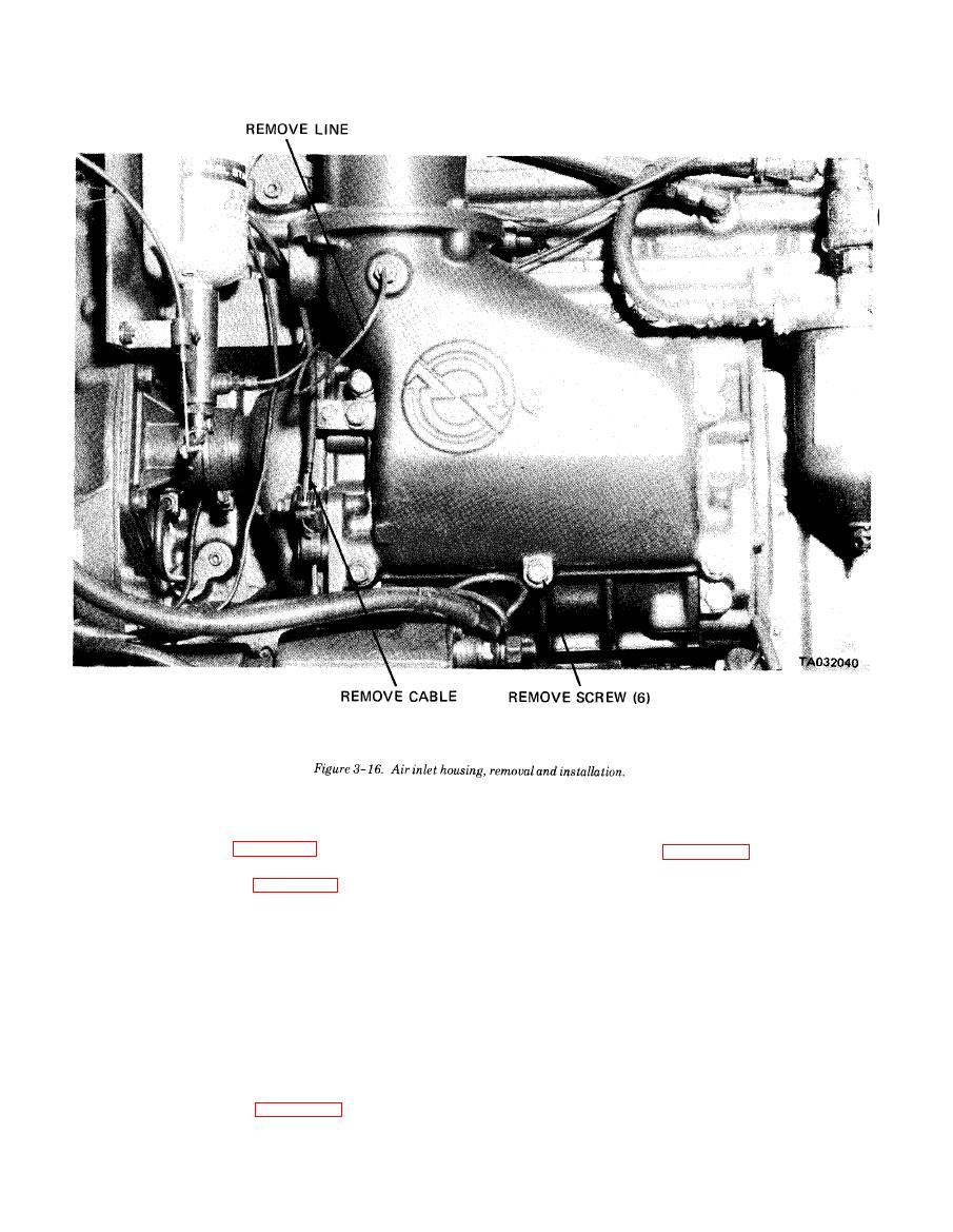
inlet housing.
air inlet housing. Tighten screws to 16-20 lbs- ft of
ble the air inlet housing in numerical sequence, noting
the position of the shutdown spring.
3-14. Blower Assembly
d. Cleaning and Inspection.
a. General.
(1) Clean air inlet housing and hardware using a
(1) The blower assembly, located behind the air in-
cleaning solvent such as P-D-680 or equivalent.
let housing, supplies fresh air required for combustion
(2) Clean the housing gasket screen of dirt and
and scavenging. Two hollow double lobe rotors revolve
foreign material. Use cleaning solvent P-D-680 and
in the rotor housing. The revolving motion of the
blow dry with low pressure compressed air.
rotors provides a continuous and uniform displace-
(3) Inspect springs for cracks and bends.
ment of air.
(4) Inspect all mounting hardware for defects and
wear. Replace a defective part.
(2) Gears located at the splined ends of the rotor
e. Reassembly. Refer to figure 3-17 and reassemble
shafts assist in spacing the rotor lobes. Normal gear
the air inlet housing in reverse of numerical sequence.
wear will have some effect on the rotor-to-rotor clear
|
|
Privacy Statement - Press Release - Copyright Information. - Contact Us |
