 |
|||
|
|
|||
|
Page Title:
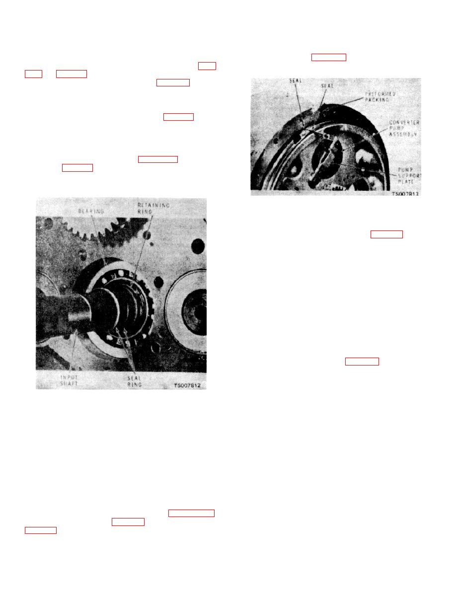
Figure 14-9. Input Shaft Installation |
|
||
| ||||||||||
|
|
 TM 10-3930-632-34
is firmly seated against the case. Install the clutch pack
the input shaft. Secure the housing to the case using the
(13 and 14) in the case so that the threaded ends of the
screws (46 and 48, fig. 14-5) and lockwashers (47).
shafts enter the bearings; secure with the nuts (1. figs.
Torque bolts to 35 to 45 ft/lbs.
h.
Install the retaining ring (35, fig. 14-2) in the
case (36). Press the bearing cup (34) into the case so
that it is firmly seated against the locating ring (35).
Install the retaining ring (7) and press the bearing (6)
firmly against the ring in the housing (50, fig. 14-5).
I.
Press the bearing (31) into the housing until it
rests firmly against its integral retaining ring. Install the
input shaft (14) in the bearing, and secure with the
locating ring (30). Make sure the two oil seals (28) are
installed on the shaft as shown in figure 14-9. Install the
stator (27, fig. 14-5), using shims (29) to take up play of
the shaft (41). Secure the stator with capscrews (26)
and lockwire.
Figure 14-10. Torque Converter Housing
Showing Pump and Seals
m.
Position the rear bearing (34, fig. 14-2) on the
pinion shaft and insert the pinion shaft part way into the
housing (36). Install the spacer (12), gear (11), and
spacer (9) on the pinion drive shaft. Seat the shaft and
install the front bearing (6), preformed packing (5), and
brake drum (3); secure with the nut (2) torqued to 150 to
200 ft/lbs. When the nut is tightened, check the rotation
of the pinion shaft. If the shaft binds, add washer (10). If
the shaft has any end play, remove washer (10). When
the proper washer thickness is obtained, the shaft shall
have a preload of 8 to 10 inch-pounds. Add shims to
decrease preload, subtract to increase preload. After
proper adjustment, install the seal (4) in the housing and
reinstall the brake drum (3) and nut (2). Secure the nut
to 150 to 200 ft/lbs and lock with the cotter pin (1).
n.
Position the gear (25, fig. 14-5) on the stator
so that the teeth of the gear mesh with those of the
converter pump drive gear (34).
o.
Insert the ball (11), spring (10) and seal (9)
into the cover plate (6); secure in place with the plug (8).
Figure 14-9. Input Shaft Installation
Insert the stop (20), regulator piston (19), pin (22), and
spring (18) into the body (21); position the washer (17)
j.
Position the gear (34) on the drive shaft of the
on the plug (16) and turn the plug into the body.
converter oil pump (35) and press the gear over the
p.
Position the washer (23) and seals (24) on the
shaft. Place the washer (33) on the shaft and secure in
body; turn the body into the cover.
place using the retaining ring (32).
q.
Position seal (2) and preformed packings (13
k.
Position the converter pump assembly on the
and 14) in the cover. Coat both sides of gasket (12) with
plate (40) and secure them together using the screws
gasket sealer and place the gasket (12) on the
(36) and lockwashers (38). Torque bolts to 20 to 25
ft/lbs. Insert the pump into the housing and secure the
plate in position using the screw (37) and lockwasher
(39).
I.
Position new seals (42 and 43) and preformed
packing (44) on the housing as shown in figure 14-10.
Position the housing (50, fig. 14-5) on the housing (36,
14-12
|
|
Privacy Statement - Press Release - Copyright Information. - Contact Us |
