 |
|||
|
|
|||
|
|
|||
| ||||||||||
|
|
 TM 10-3930-632-34
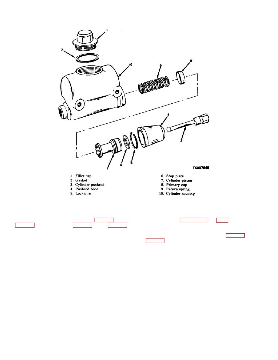
Figure 11-3. Inching Brake Master Cylinder, Exploded View.
11-9.
Cleaning and Inspection
11-10.
Reassembly
a. Discard the primary cups (10, fig. 11-2, and 8,
a. Refer to figures 11-2 and 11-3 and reassemble
the service and inching brake master cylinders.
b. Clean all other metal parts of the brake master
Note the following:
b. After installing the spring (11, fig. 11-2, and 9,
cylinder in denatured alcohol; dry thoroughly with
compressed air.
c. Inspect the tank for cracks, distortion, and
tank, lock them in place with the stop plate and lockwire
retainer.
damaged threads. Check the bore of the tank for pitting
or scoring. Replace if damaged.
d. Inspect all other parts for cracks, damaged
11-11.
Installation
threads, distortion, and other damage; replace damaged
Install the brake master cylinders, bleed the brake
parts.
system and adjust the brake linkage (TM 10-3930-632-
12).
Section IV. WHEEL CYLINDERS
When brake fluid under pressure is applied to the wheel
11-12.
General
cylinder, both pistons are pushed outward in the cylinder,
The wheel cylinders are mounted on the brake
forcing the brake shoes apart. This
backing plate, positioned between the brake shoes.
11-4
|
|
Privacy Statement - Press Release - Copyright Information. - Contact Us |
