 |
|||
|
|
|||
|
Page Title:
Section III. REPAIR OF DRIVE CONTROL COMPONENTS |
|
||
| ||||||||||
|
|
 TM 10-3930-631-34
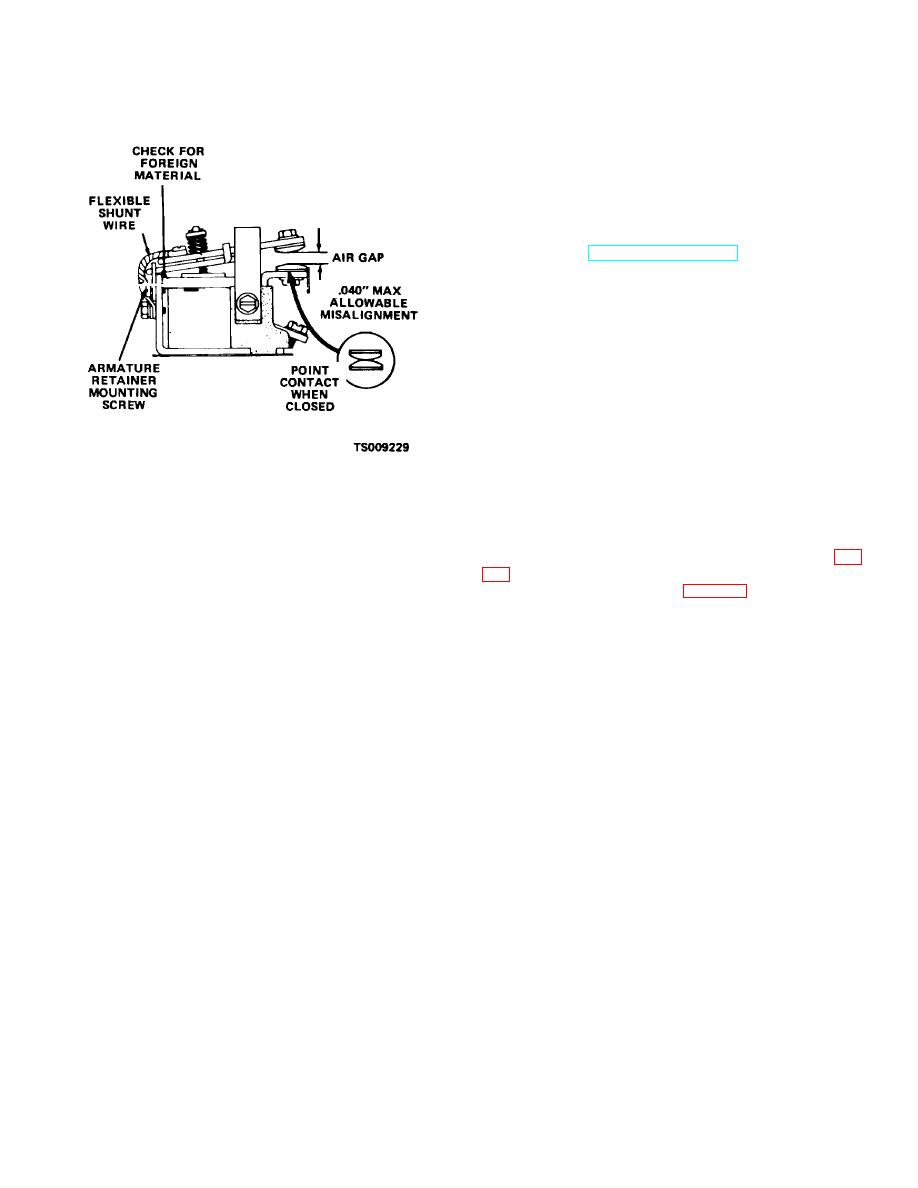
c. Inspect the junction of the armature and the
armature retainer for foreign material which may be
lodged between them.
d. Inspect the control valve linkage and pump
switches to make certain the pump motor operates
before the hydraulic system is activated.
e. Resolve excessive clearance in the control valve
linkage by checking for worn or missing cotter pins, yoke
pins, washers, and yokes.
f. Refer to TM 10-3930-631-12 to replace
contactor points.
Figure 9-13. Contactor and points.
Section III. REPAIR OF DRIVE CONTROL COMPONENTS
b. Removal.
9-22. Accelerator Control
(1) Disconnect the wiring harness connector fig.
a. General. The accelerator control box is mounted
below the instrument panel on the front frame of the
(2) Remove screw (9, fig. 9-14), nut (11) and
truck.
lock washer (10) securing bearing to frame.
9-18
|
|
Privacy Statement - Press Release - Copyright Information. - Contact Us |
