 |
|||
|
|
|||
|
Page Title:
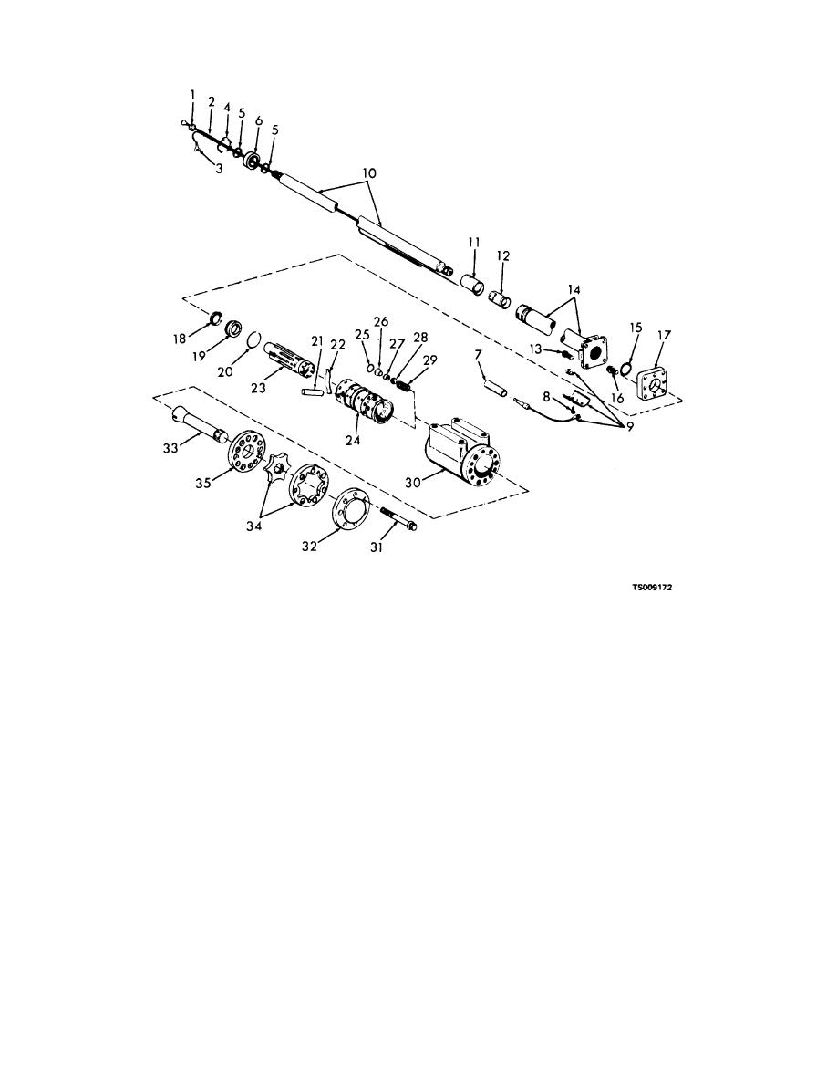
Figure 5-4. Steering valve unit, exploded view. |
|
||
| ||||||||||
|
|
 TM 10-3930-631-34
1.
Insulator
8. Screw
15.
Seal
22.
Centering spring
29.
Spring
2.
Electrical lead
9. Brush assembly
16.
Screw
23.
Spool
30.
Housing
3.
Electrical lead
10. Shaft
17.
Plate
24.
Sleeve
31.
Screw
4.
Retaining ring
11. Contact ring
18.
Seal
25.
Packing
32.
Cap
5.
Retaining ring
12. Insulator
19.
Bushing
26.
Plug
33.
Gear
6.
Bearing
13. Screw
20.
Packing
27.
Seat
34.
Gerotor set
7.
Connector
14. Flanged tube
21.
Centering pin
28.
Ball
35.
Gerotor plate
Figure 5-4. Steering valve unit, exploded view.
(3) Remove retaining rings (4 and 5) and
screws. Remove steering column from lower valve
push shaft free of bearing. Remove bearing (6) and
unit.
second retaining ring (5).
(5) Remove screws (8) and remove brush
(4) Mark location of screws (13) and
remove
5-7
|
|
Privacy Statement - Press Release - Copyright Information. - Contact Us |
