 |
|||
|
|
|||
|
Page Title:
Cleaning, Inspection and Repair. |
|
||
| ||||||||||
|
|
 TM 10-3930-631-34
assemblies (9). Remove ring (11) and insulator (12)
from shaft (10) and flange (14).
(6) Clamp valve unit in a vise and remove
screws (31). Remove cap (32), gerotor set (34),
plate (35) and drive gear (33) as a unit.
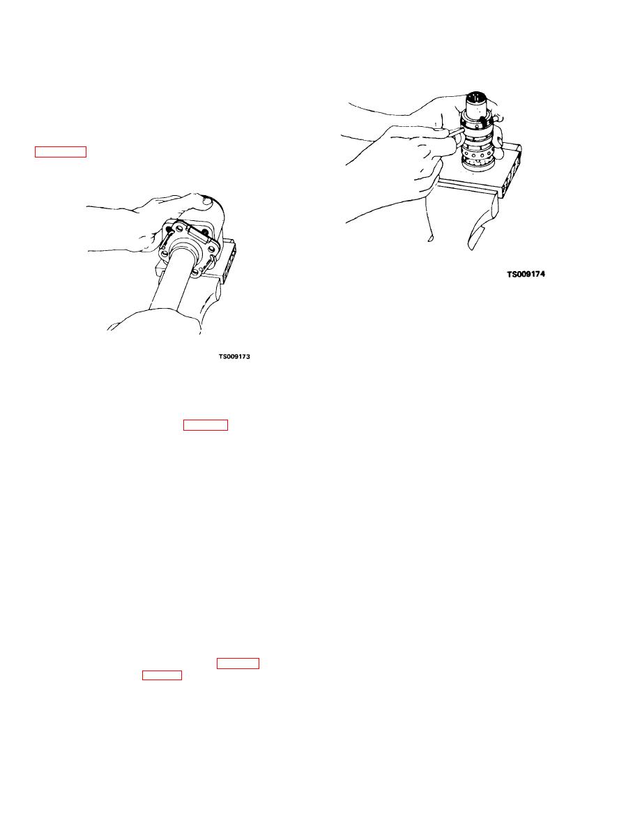
(7) Remove unit from vise and insert splined
end of column assembly into lower unit as shown in
control spool and sleeve parts. Spool should rotate
freely.
Figure 5-6. Loosening spool assembly.
(14)Push inside lower edge of spool so
spool moves toward splined end and remove spool
(23) carefully from sleeve.
(15)Push centering spring (22) out of spool.
(16)Remove gear (33), gerotor set (34) and
Figure 5-5. Checking spool rotation.
plate (35) from end cap (32).
c. Cleaning, Inspection and Repair.
(8) Place a wooden block in vise to support
(1) Clean all metal parts in cleaning com-
spool parts. Clamp unit across port face with control
pound, solvent (Fed. Spec. P-D-680). Place parts
end up. Remove screws (16, fig. 5-4). Hold the
on clean lint free cloth or paper and allow to air dry.
spool assembly down against the wooden block and
(2) Inspect surfaces of all moving parts for
remove mounting plate (17). Remove seals (15 and
scoring and other damage.
18) and discard seals. Remove bushing (19) and
(3) Slightly scored parts can be cleaned by
packing (20). Discard packing.
hand rubbing with fine abrasive paper.
(9) Place housing securely on a solid
(4) Prepare surfaces of gerotor set and
surface with the port face down. Remove pin (21),
plates as follows:
spring (22), spool (23) and sleeve (24) as an
(a) Place a sheet of fine (600 grit) abrasive
assembly. Use care when removing assembly.
paper, face up, on a piece of plate glass or similar
Parts are closely fitted and must be rotated slightly
smooth, flat surface.
as they are withdrawn.
(b) Clean ends of star gear (part of gerotor
(10)Use a small bent tool or wire and
set) by stroking it across the abrasive. This will
remove check valve plug (26) from housing. Do not
remove any sharp grit which could scratch other
pry against edge of hole in housing bore. Remove
components.
packing (25) and discard.
(c) Stroke each side of ring gear (part of
(11)Use a 3/16 inch (4.76 mm) hex wrench
gerotor set), both sides of gerotor plate and
and remove check valve seat (27) from housing.
mounting plate and the inner side of end cap.
(12)Turn the housing over and tap lightly to
(d) Hold parts as flat as possible against the
remove ball (28) and spring (29) from bore in
abrasive. Small bright areas on the faces indicate
housing.
burs which must be removed. After 6 to 10 strokes
(13)Hold the spool assembly (fig. 5-6) and
across abrasive check to see if part is polished. All
push the cross pin (21, fig. 5-4) to loosen it from the
parts should have smooth polished surfaces. After
spool and sleeve. Remove pin.
polishing each part, clean in solvent and blow dry
with air. Place parts in absolutely clean area to await
assembly.
5-8
|
|
Privacy Statement - Press Release - Copyright Information. - Contact Us |
