 |
|||
|
|
|||
|
Page Title:
CHAPTER 5 REPAIR OF STEERING- SYSTEM |
|
||
| ||||||||||
|
|
 TM 10-3930-631-34
CHAPTER 5
REPAIR OF STEERING- SYSTEM
Section I. DESCRIPTION AND PRESSURE CHECK
5-1. Description
a. The steering system of the lift truck is
hydraulically powered. A separate hydraulic pump
supplies pressure to actuate the system (fig. 3-1).
b. Main components of the system are the steering
hydraulic pump, the steering valve unit and the steering
cylinder. Oil for the system is supplied from the main
hydraulic reservoir. Rotation of the steering wheel opens
ports in the steering valve unit and transmits pressure to
the cylinder. The piston in the cylinder moves under the
pressure, extending or retracting the cylinder rod. The
cylinder rod is connected to a drag link which in turn
actuates the steering axle pivot arm. Movement of the
pivot arm pulls or pushes the tie rods which are attached
to the spindles. As the wheels are mounted on the
spindles the wheels turn guiding the truck in the direction
desired.
5-2.Steering Pressure Check and Adjustment
a. Pressure Check. Check and adjust system
pressure as follows:
(1) Drive truck up on ramp or raise truck on a
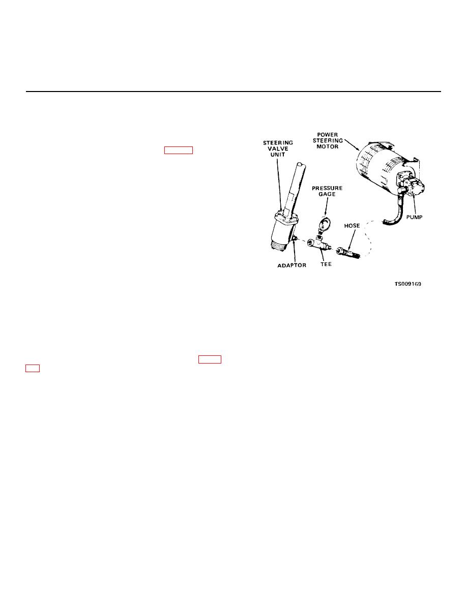
Figure 5-1. Pressure gage location.
suitable lift to gain access to pump.
(2) Remove floor and toe plates to gain access
(5) Connect the battery, depress the seat to
to the steering valve unit.
close the switch and turn the master switch on. Pump
(3) Disconnect the pressure hose from the
motor will run continuously while master switch is on and
pump to the adapter in the steering valve unit at the
seat is occupied.
adapter.
(6) Turn wheel right or left and place a block
(4) Install a suitable tee fitting as shown in figure
between spindle and steer axle. Turn steering wheel to
force steering wheel against block. Observe needle on
(0-210.9 kg/cm2 ) in the tee.
pressure gage. If pressure of
5-1
|
|
Privacy Statement - Press Release - Copyright Information. - Contact Us |
