 |
|||
|
|
|||
|
|
|||
| ||||||||||
|
|
 TM 10-3930-630-34
slightly below surface and that surface is clean.
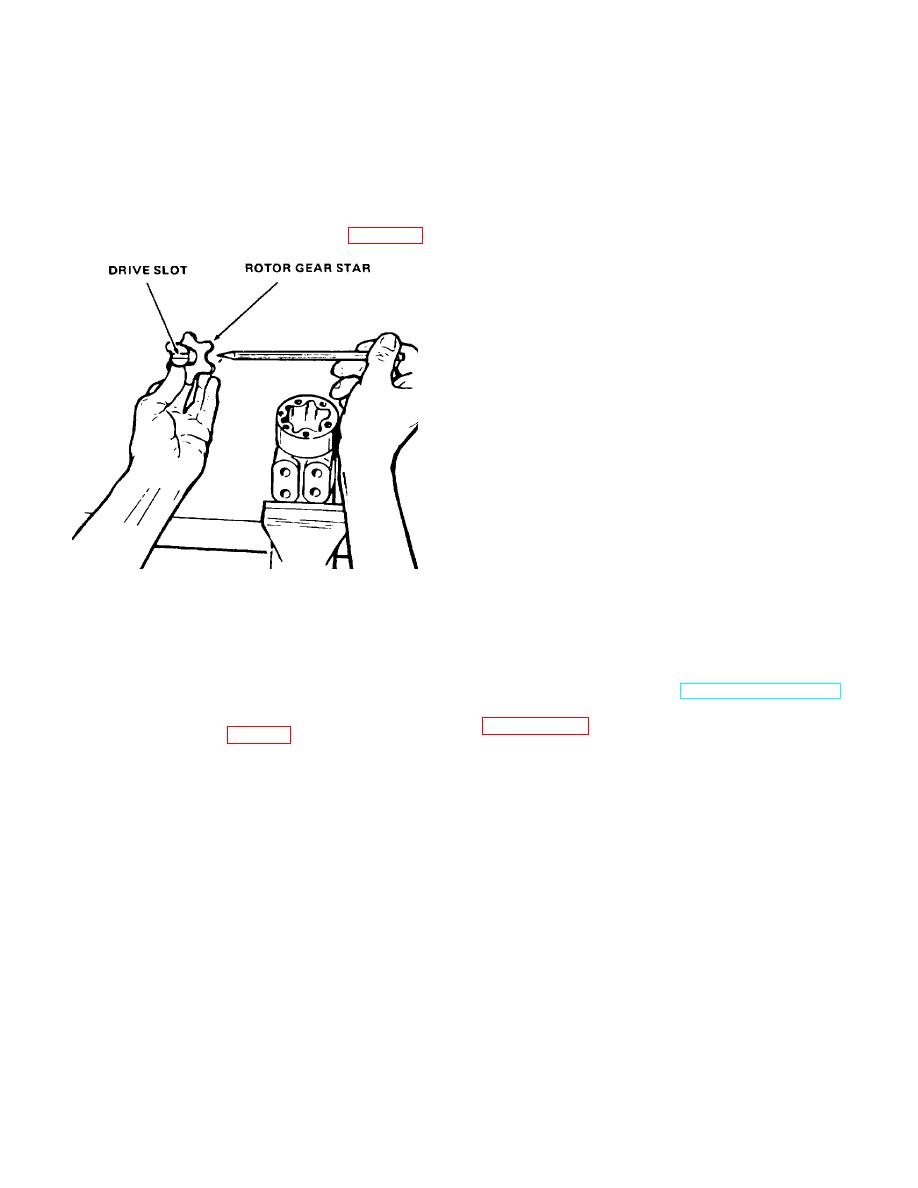
the proper valve timing of the unit.
(3) Place end plate (20) over control spool and
There are 12 teeth on the spline and
sleeve. Align holes in plate with tapped holes in
6 on the gear. Alignment will be
housing.
right in 6 positions and wrong in 6
(4) Install rotor (19) on assembly and align screw
positions. Should the parts slip out
holes.
of position during installation, make
(5) Place splined end of drive shaft (21) in rotor
certain it is corrected.
splines. Slot in end of drive shaft must be aligned with
(7) Install drive shaft and rotor into rotor ring (19),
outside diameter valleys of gear as shown in figure 8-7.
drive shaft first, and slowly rotate until cross slot in drive
shaft engages cross pin. Splined end of drive shaft will
drop against rotor when slot engages pin.
(8) Place end cap (18) over assembly and install
screws (17), finger tight, to maintain alignment of parts.
(9) Secure assembly in vise and torque screws to
150 inch pounds (18.5 N ).
m
d. Column Reassembly.
(1) Note match marks on column (14) and secure
column to mounting plate with screws (13). Torque
screws to 280 inch pounds (7728.0 cm/g).
(2) Install retaining ring (12), bearing (11), and
second retaining ring (10) on shaft (9).
(3) Install horn wire (4) through washer (7), spring
(6), ferrule (5) and partially through shaft (9). Bring wire
out of shaft and connect to contact ring (15).
(4) Insert insulator (16) into contact ring and slide
both parts, gradually pulling back on horn wire, on shaft
(9).
(5) Insert shaft into column (14) and secure with
TA067426
large retaining ring (8). Rotate shaft to engage splines
Figure 8-7. Drive shaft alignment.
on shaft with splines in spool.
(6) Install brush assembly (2) on column with
(6) Push splined end of drive shaft (21) through
brushes in contact with contact ring. Secure brush
rotor until spline extends about one-half its length
assembly with screws (1).
beyond rotor surface. Note position or direction of cross
(7) Install connector (3) on brush wire.
pin (34) in the assembly.
e. Installation. Refer to TM 10-3930-630-12 and
CAUTION
install steering wheel and horn button.
Refer to
Alignment of cross slot in shaft with
valleys of gear (fig. 8-7) determines
8-8
|
|
Privacy Statement - Press Release - Copyright Information. - Contact Us |
