 |
|||
|
|
|||
|
|
|||
| ||||||||||
|
|
 TM 10-3930-630-34
in the pressure side of the steering circuit.
system to fill. Check for pressure of air leaks in the
system. After running for one minute, shut engine off
b. Operate pump at full engine speed, and
turn the steer wheels to their limit. The opening pressure
and recheck oil level. If low, fill to proper level. Refer to
LO 10-3930-630-12 for proper grade oil.
must be set at 1100 psi (77.3 kg/cm2). Adjust the pump
relief valve setscrew in or out to set opening pressure.
(3) Refer to paragraph 3-21 and set the
main hydraulic relief pressure (in control valve) to 1900
to 2000 psi (133.5 to 140.6 kg/cm2)
NOTE
Always start the hydraulic pump
3-26.
Hydraulic Pump, Relief Valve Adjustment
under no load conditions to prolong
a. Install a pressure gage (2000 psi) (140.6
pump life.
kg/cm2)
Section VII. MAST AND CARRIAGE
3-27. Description
3-28.
Hydraulic Carriage, Removal and
The mast and carriage support, and lift the load. Both
Disassembly
are of welded construction. Studs to mount the bearings
a. Removal. Refer to TM 10-3930-630-12 and
are welded to the mast and carriage.
remove the carriage.
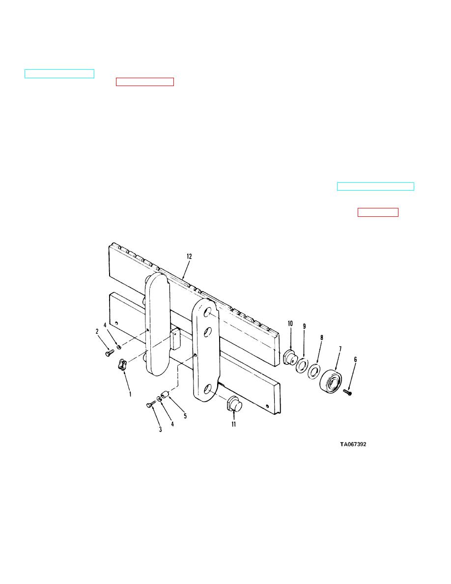
b. Disassembly. Disassemble the carriage in
numerical sequence as illustrated on figure 3-10.
1 Chain link
7 Bearing
2 Screw
8 Shim
3 Screw
9 Shim
4 Cock washer
10 Stud
5 Spacer
11 Stud
6 Screw
12 Carriage frame
Figure 3-10. Hydraulic carriage, disassembly and reassembly.
3-16
|
|
Privacy Statement - Press Release - Copyright Information. - Contact Us |
