 |
|||
|
|
|||
|
|
|||
| ||||||||||
|
|
 TM 10-3930-630-12
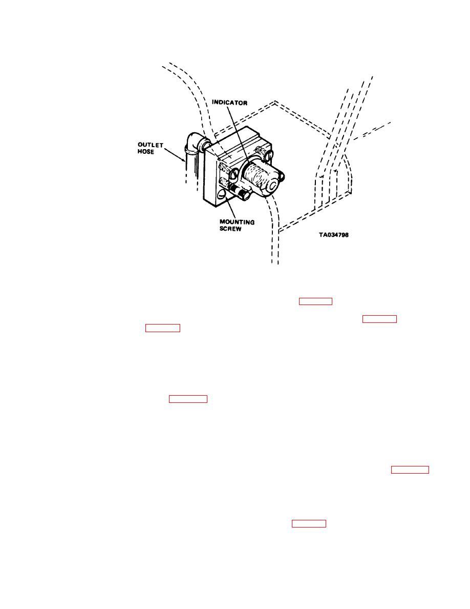
Figure 4-23. Hydraulic filter element indicator, installed view.
filter housing. (fig. 4-24).
(2) Remove screws, lockwashers and nuts
(3) Remove hydraulic filter housing.
securing indicator to bracket and remove indicator.
d. Installation.
Remove packing from filter head (fig. 4-24).
(4) Remove filter element from housing.
(1) Install indicator (fig. 4-23) in position
(5) Clean inside of filter body and filter
on bracket. Secure indicator with screws, lockwashers
head with cleaning compound, solvent (Fed. Spec. P-D-
and nuts.
680) and dry thoroughly.
(2) Remove plugs from indicator and
(6) Install new filter element in filter
hoses. Connect hoses to indicator.
housing.
(3) Check oil level in reservoir and fill to
(7) Install new packing in filter head and
proper level Refer to current lubrication order for
install housing and filter element by screwing housing
correct oil
into head.
(4) Bleed hydraulic system (para 4-34).
(8) Tighten housing to 20 to 30 pound-feet
(5) Operate truck and observe indicator.
(27.1 to 40.6 N-m).
Indicator should register filter element condition.
(9) Check oil level in hydraulic reservoir
4-43.
Hydraulic Filter
and add oil if necessary. Refer to current lubrication
order for correct oil.
a. General. The hydraulic filter is mounted at
(10) Operate hydraulic system and check
for leaks. Correct leaks if necessary.
the right front of the truck. All hydraulic oil flows from
(11) Bleed hydraulic system (para 4-34).
the control valve and steering valve through the filter
(12) Install right front cowl
and returns to the reservoir.
c. Filter Replacement.
b. Service.
The filter element must be
(1) Removal.
replaced at intervals shown on the current lubrication
(a) Remove right front cowl
order. It should also be replaced at any time the filter
(b) Disconnect
steering
system
element indicator shows flow through the element is
return hose (fig. 4-24) from elbow at inlet hose (fig. 4-
restricted. To replace the element, proceed as follows:
24). Remove elbow and packing from inlet elbow.
(1) Remove attaching parts and remove
right front cowl
(2) Place a suitable container below filter.
Use an appropriate wrench on the large hex on hydraulic
4-33
|
|
Privacy Statement - Press Release - Copyright Information. - Contact Us |
