 |
|||
|
|
|||
|
|
|||
| ||||||||||
|
|
 TM 10-3930-628-12
(3) Tighten switch mounting screws to secure
adjustment.
c
Removal. To remove interlock switch (5, fig.
mounting screws (8), nuts (20) and lock washers (9).
d. Installation. Install interlock switch (5, fig.
washers (9). Connect wires (1I and 4) to switch. Adjust
switch operation ( b above).
4-36. Service Brake Brake Shoes
a. General. The service brake brake shoes
are mounted behind the dust shield. The shoes are
attached to the wheel cylinders and return springs. The
brakes are self-adjusting.
b. Removal.
(1) Refer to paragraph 4-39 and remove the
front drive wheel and tire assembly.
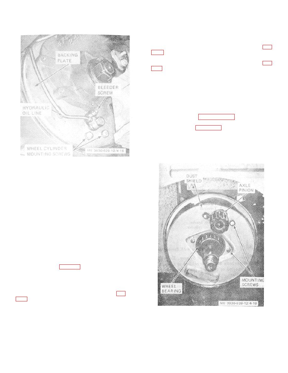
(2) Refer to figure 4-19 and remove brake dust
shield as follows:
(a) Remove four screws and lock washers
securing dust shield to axle. Remove wheel bearing
from axle.
(b) Carefully remove dust shield from around
Figure 1-18. Service brake system bleeder screw.
axle pinion.
(3) Repeat Open the bleeder screw one turn.
(4) Slowly depress brake pedal to end of travel
and release pedal. Repeat several times. Observe
Cause in jar and repeat pumping of brake pedal until no
air bubbles escape from hose. Hold pedal at bottom of
travel and close bleeder screw to keep additional air from
entering system.
Note. While pumping pedal check fluid level in
master cylinder. Add fluid to keep cylinder as close to
full as possible at all times
(5) Close bleeder screw and disconnect hose.
Repeat operation on bleeder screw on other front wheel.
(6) Fill master cylinder to proper level after
bleeding operation. Replace filler.
Caution: Discard fluid salvaged from brake
system during bleeding operation. Do not use in system.
4-35. Brake Interlock Switch
a. General. The brake switch is operated by a
switch actuator (17, fig. 4-17) Brake pedal should move
about one inch before switch is opened. Depress brake
pedal and check switch operation. If adjustment is
necessary, adjust as follows:
b. Adjustment.
(1) Loosen switch mounting screws (8, fig.
(2) Slide switch toward rear of truck to shorten
pedal travel before switch action or toward front of truck
Figure 4-19. Service brake dust shield, installed view.
to lengthen pedal travel.
4-20
|
|
Privacy Statement - Press Release - Copyright Information. - Contact Us |
