 |
|||
|
|
|||
|
|
|||
| ||||||||||
|
|
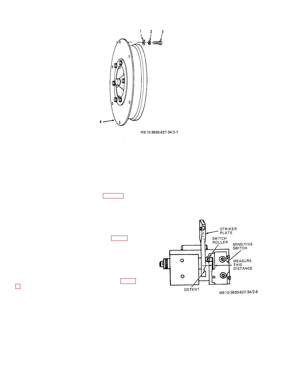 1.
Flat washer
2.
Lock washer
3.
Screw
4.
Torque converter
Figure 2-7. Torque converter
(b) At this point mea ure the distance
s
b. Installation.
between the switch body and roller arm with a feeler
(1) Install the torque converter on the engine
gage.
flywheel, with timing marks on drive plate next to hole in
(c) Subtract 3/32 inch from feeler gage
flywheel marked on removal. (see note, para 2-7).
(2) Reverse the removal procedure (a. above).
reading, repeat ( ) above, and tighten switch in this
b
Be careful to keep the clutch spline shaft aligned with
position.
the splines in the hub of the torque converter during
installation, to prevent binding.
(3) After completing installation, and linkages are
connected, adjust inching controls as follows:
(a) Attach pressure gage (0-250 psi range) to
forward clutch pressure port (for location see fig. 7-4).
(b) Adjust the adjusting screw in the inching
valve in or out as required to obtain maximum forward
clutch pressure with the brake pedal in the fully released
position (foot off brake).
(c) Disconnect pressure gage, install pipe
plug in pressure port, and tighten adjusting screw lock
nut.
(4) Adjust neutral safety switch as follows (fig. 2-
(a) With the switch roller just contacting the
flat area of the striker plate which actuates it, adjust the
switch position until the switch clicks.
Figure 2-8. Neutral safety switch adjustment.
2-10
|
|
Privacy Statement - Press Release - Copyright Information. - Contact Us |
